Causes of Pressing Defects (Burrs, Dents) and Observation of Defects and Cut Sections (Fracture Surfaces)
Pressing is widely used in the mass production of various products. With the progression of electronic control in automobiles, there are demands for higher accuracy, durability, and reliability of vehicle frames, sliding parts, and electrical parts, which are being miniaturised and installed with higher density.
Within this section, you'll learn about that causes and countermeasures of pressing defects. It also includes examples of how our 4K digital microscope improves the observation of defects and cut sections, such as fractured surfaces. The examples are from the testing, design, and prototyping of research and development and inspections carried out in quality assurance.
- Causes of and Countermeasures for Pressing Defects
- Observation Examples of Cut Sections and Defects on Pressed Products
- A Microscope That Optimises the Research and Development, Design, and Quality Assurance of Pressed Products
Causes of and Countermeasures for Pressing Defects
Pressing types
In pressing, the material is shaped through the application of pressure using various methods, generally with a mould called a die and punch.
- Shearing: The material is processed (cut) through the application of force exceeding its fracture limit.
- Bending: The material is bent through the application of tensile force on one side and compression force on its other side.
- Deep drawing: The material is processed through the application of tensile stress.
- Compression: The material is processed through the application of compression force.
Causes of and countermeasures for typical pressing defects
It is difficult to completely and continuously eliminate all defects due to the properties of the material, design, and processing principles. However, it is important to improve the yield rate as much as possible by reducing the frequency of defects through various countermeasures.
- Burrs
- Cause: The gap (clearance) between the punch and die is too large during shearing.
Countermeasure: Ensure that 1/2 to 1/3 of the plate thickness is the sheared surface and is uniform.
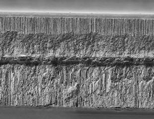
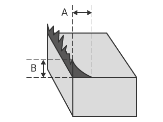
Structural images of the material's cross-sections after shearing with various clearance conditions are shown below, including explanations of the names and characteristics of the parts.
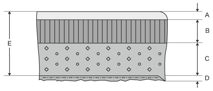
- Shear droop: Smooth surface caused by the surface of the material being pulled.
- Sheared surface: Glossy surface with vertical stripes. There are subtle scratches caused by the punch cutting during shearing and friction between the deposited metal and the material.
- Fracture surface: Compared to the sheared surface, this is a rougher surface that has been torn away, making the surface extremely uneven.
- Burr: A jagged protrusion from the material. Large burrs can lead to defective products due to insufficient fit accuracy between parts and safety problems such as injuries caused by sharp burr tips.
- Plate thickness
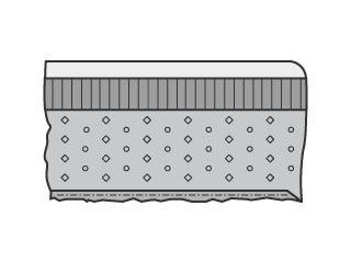
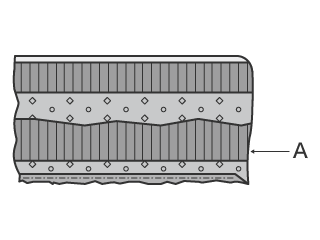
Too much clearance and extraction pressure results in a larger burr and warping causing the shape and dimension accuracies to decrease. On the other hand, too little clearance causes a secondary sheared surface (A in the figure on the right) on the other side of the fracture surface to occur, resulting in whisker-shaped burrs.
The size of a burr is expressed as the thickness of its base (A in this figure) or as its height (B in this figure).
- Springback
- Cause: After bending, the residual compressive stress and tensile stress in the material act in opposition to each other, causing the processed part to bend back toward its original shape.
Countermeasures: Bend to a deeper angle than intended or add a striker plate or a notched groove to the punch.
- Wrinkles
- Cause: This happens when compression force is applied to the flange during deep drawing.
Countermeasure: Use wrinkle suppression via the deep drawing conditions to apply a uniform load to the material. In addition to fixed wrinkle suppression, there is also moveable wrinkle suppression that uses the force of a spring or a die cushion.
- Cracks
- Cause: Cracks form in the material when the tensile force exceeds the fracture limit during deep drawing.
Cracks, splits, and tears may occur during bending due to the rolling direction of the material or the bend width dimension.
Countermeasures: In deep drawing, reduce the wrinkle suppression pressure or make the curve of the die smooth to lower the deformation resistance. In bending, ensure that the bending line and the rolling direction of the material are perpendicular or set the bend width to at least eight times the plate thickness.
- Scrap buildup (the cause of dents and scratches)
- Cause: When scrap (which should be removed from the mould) affixes to the punch due to vacuum pressure, oil films, and magnetism after extraction processing. Scrap buildup is the cause of defects such as dents and scratches on the material surface and may also damage the mould.
Countermeasures: Install a kicker pin on the punch to establish a physical gap between the scrap and the punch. Other methods include discharging air from the tip of the punch, cutting a groove in the punch and inserting air there, and suctioning the scrap from below. It may also be possible to reduce the degree to which scrap affixes to the punch by lowering the viscosity of the oil used or by cutting a groove in the punch to reduce the contact area of the oil.
Observation Examples of Cut Sections and Defects on Pressed Products
Sometimes, pressing defects cannot be avoided just by working hard at a production site. It is necessary to strive for improvements through repeated testing and prototyping during research and development, material selection, and product/mould design. In quality assurance, it is also important to research the causes of metal part malfunctions produced through pressing and to improve these parts.
Therefore, detailed observation of defects with a microscope is vital.
For example, a microscope can be used to check whether the processing conditions were appropriate from the cut section, during shearing, and whether burrs can be attributed to these conditions.
On the other hand, processed metal components are three dimensional, which makes them difficult to observe because it is hard to focus the entire object and because the surface roughness and reflectance vary within the same field of view.
This section explains the advantages of the VHX Series 4K digital microscope using examples of microscopic surface differences such as shear droop, sheared surfaces, and fracture surfaces from the cross sections of a pressed product and defects such as burrs and dents.
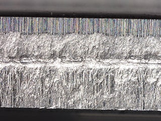
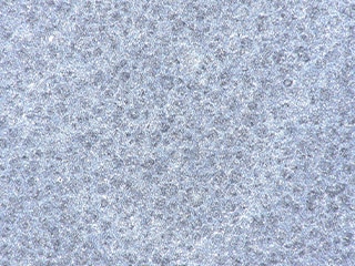
Observation of pressed product cross sections (shear droop, sheared surfaces, fracture surfaces)
The cross section of a sheared pressed product can be used to evaluate whether the clearance between the punch and die is appropriate, the ratio of the sheared surface to the plate thickness, the processing quality, and the causes of burrs. The surface conditions—such as the depressions and projections, the roughness, and the pattern—vary for the shear droop, sheared surfaces, and fracture surfaces that appear in the cross section. Furthermore, although each part has the same colour and low contrast, the light reflectance varies, making it difficult to observe the overall surface conditions.
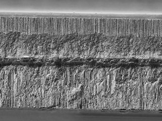
The VHX Series 4K digital microscope is equipped with features that provide both high resolution and large depth of field such as a telecentric HR lens and a 4K CMOS image sensor, ensuring that this microscope has the best resolution in its class. Hence, fully-focused images of the entire cross section can be captured even when the same cross section has various surface conditions.
By combining our specially designed optics, 4K CMOS image sensor, and Optical Shadow Effect Mode, users can easily capture images from various lighting directions to analyse microscopic surface irregularities and other surface conditions with high contrast. Optical Shadow Effect Mode is a new observation method that uses lighting to capture subtle irregularities on a surface, even at low magnifications! The images can be combined with colour information to quickly visualise depth and height information.
The VHX Series can utilise this advanced observation method with simple operations, increasing the speed of cross section observation and evaluation.

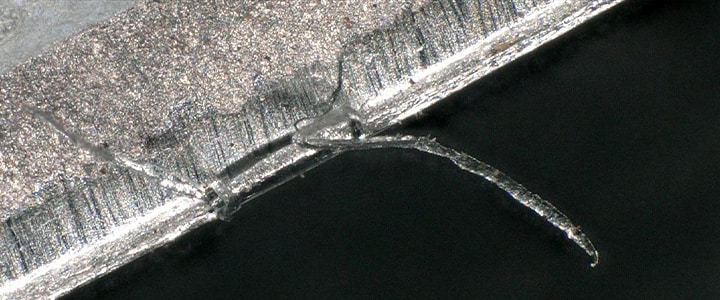
Fully focused observation of microscopic burrs
Even though burrs on pressed products are small, they are hard and sharp making the product less safe. Burrs may get caught during part assembly, negatively affecting the production yield rate.
In investigating the cause of a burr, the most important information is its base and tip, but it's difficult to observe both of these aspects clearly at the same time with conventional microscopes because burrs are three-dimensional and microscopic, meaning that it was only possible to bring a part of them into focus at a time.
KEYENCE’s cutting-edge optical technology and unique observation system allows three-dimensional targets to be observed within one fully-focused image.
The lens, 4K CMOS image sensor, and ring illumination—which provide high resolution and a large depth of field—allow even whisker-shaped burrs to be observed in focus from its base to its tip.
The overall image of a defect can be viewed at a glance with a fully-focused image, optimising the workflow of cause investigation via observation.
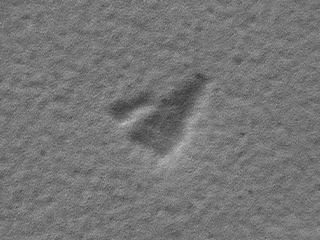
High-contrast observation of dents and other microscopic defects
Minor dents and microscopic scratches caused by scrap buildup and similar defects have minimal contrast with the background when the material is metal. Therefore, it is difficult to determine optimum lighting conditions and there were cases where these dents and scratches could not be detected.
With the VHX Series 4K digital microscope, there is no need to manually determine conditions. With just one click of a button, the operator can select the image that is most suitable using the Multi-lighting function, which automatically acquires omnidirectional lighting data. Even after selecting an image, the images with the other lighting conditions are saved automatically, allowing for observation under different conditions without having to place the sample on the stage again.
Another method to quickly observing microscopic dents with high contrast is Optical Shadow Effect Mode, a new observation method that easily captures images that rival a scanning electron microscope (SEM) at low magnification.
A Microscope That Optimises the Research and Development, Design, and Quality Assurance of Pressed Products
Even for experienced operators, observations of cross sections and microscopic defects of pressed products were conventionally difficult and time consuming due to the characteristic glossiness of the metal materials used to make these products. Now with the VHX Series 4K digital microscope, users can quickly observe and capture fully-focused images.
The images captured using the VHX Series digital microscope's diverse functions improve observation vital to research and development, product and mould design, and quality assurance in the event of product malfunctions.
For additional info or inquiries about the VHX Series, click the buttons below.
