Observation and Measurement after Thermal Spraying Using Digital Microscopes
Thermal spraying is a surface treatment technique that forms a functional coating on parts surfaces by spraying melted materials such as metals, ceramics, and cermets. This technique is used for various purposes such as improving wear resistance, corrosion resistance, and insulation properties and restoring dimensions. This section introduces examples of how to use digital microscopes to observe and measure surfaces and coatings after thermal spraying.
- What is Thermal Spraying?
- Characteristics of Thermal Spraying
- Purposes and Effects of Thermal Spraying
- Typical Thermal Spraying Methods
- Observation and Measurement Examples after Thermal Spraying Using Digital Microscopes
What is Thermal Spraying?
Thermal spraying is a surface modification technique that forms a functional coating by applying materials as a spray. Materials, such as metals, ceramics, and cermets, are melted with gases or electricity and sprayed onto part surfaces. The sprayed melted particles cool instantaneously to form a functional coating.
Characteristics of Thermal Spraying
- Parts surfaces made from any material, such as metals, ceramics, and plastics, can be processed.
- A wide variety of materials to spray can be selected, such as metals, ceramics, and cermets.
- The heat effect is low and there is almost no thermal deformation.
- There is no limit to part dimensions.
- Thermal spraying can be performed only on required areas.
- Immovable objects, such as piers, can be treated on-site.
Purposes and Effects of Thermal Spraying
- Rust prevention, corrosion prevention, chemical resistance
- Prevention of corrosion caused by rust formed due to outdoor use and corrosion caused by chemical reactions
- Heat resistance, heat insulation
- Prevention of high-temperature corrosion and temperature increase on part surfaces
- Lubrication, wear resistance
- Porous coatings provide high lubrication performance, improving durability.
- Conductivity, insulation
- It is possible to improve conductivity by spraying metals and insulation properties by spraying ceramics.
- Dimensional restoration
- It is possible to restore parts damaged due to wear or corrosion, and correct dimensions by overlaying materials.
- Non-adhesion treatment
- Prevention of adhesion to tacky materials
Typical Thermal Spraying Methods
Oxygen fuel spraying
- Flame spraying
- This thermal spraying method melts and accelerates thermal spray materials in a combusting flame in air filled with combustible gases, such as acetylene, and oxygen. There are two variations: powder flame spraying and wire flame spraying.
- High velocity flame spraying
- This method allows thermal spraying materials to collide with the target material at supersonic speed by combusting liquid fuel (kerosene) and oxygen to form the coating.
Electric spraying
- Electric arc spraying
- This thermal spraying method generates an arc between the tips of two metal wires (thermal spraying materials) to melt them and blows the melted materials with a compressed air jet.
- Plasma spraying
- This thermal spraying method feeds thermal spraying materials to a plasma flame and allows the materials to collide with the target material at supersonic speed to form the coating.
Observation and Measurement Examples after Thermal Spraying Using Digital Microscopes
These are the latest examples of observation and measurement after thermal spraying using KEYENCE’s VHX Series 4K Digital Microscope.
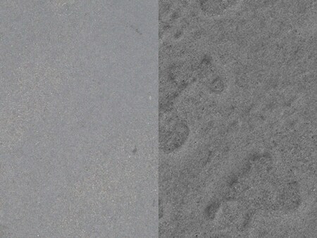
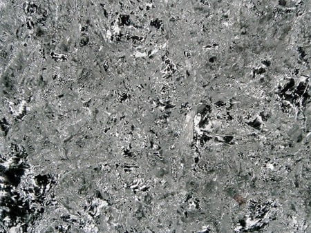
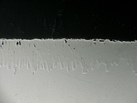
VHX-E20, 80×, ring illumination
Left: Normal image
Right: Optical Shadow Effect Mode image
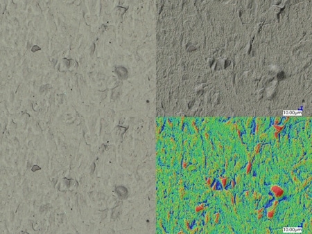
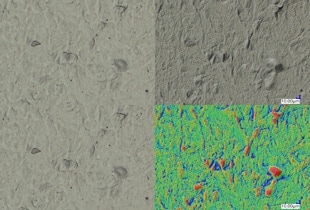
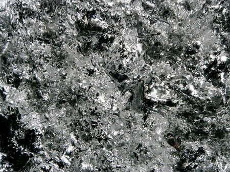
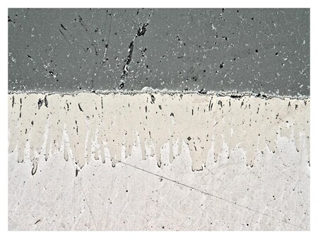
VHX-E100, 300×, coaxial illumination
Left: Normal image
Upper right: Optical Shadow Effect Mode image
Lower right: Colour Map image
Surface observation after thermal spraying
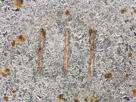
ZS-200, 200×, ring illumination, multi-lighting
Observation of scratches on a thermal spray coating
ZS-20, 150×, ring illumination + multi-lighting
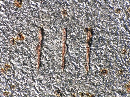
Observation of a thermal sprayed coating
VH-Z500, 500×, coaxial illumination + HDR
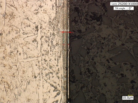
Thickness measurement of a thermal spray coating
ZS-200, 1000×, coaxial illumination