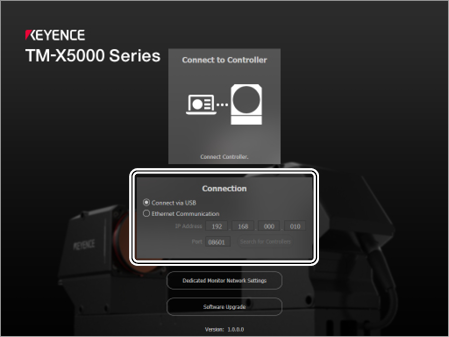
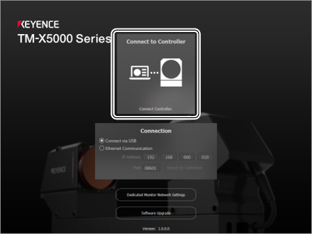
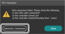
When the controller is connected for the first time, it may perform a restart.
When a connection cannot be established due to waiting for the controller to startup or some other reason, selecting [Automatic Connection] will continue to try to connect until the controller can be connected to.
To stop the operation, turn off the power to the controller.
Turning off the controller while it is accessing an SD memory card may damage the card itself and/or corrupt the data that is being saved on the SD memory card.
Basic Operation of the Tool Settings
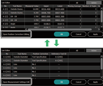
The tools for [Position Correction] and [Measurement Settings] are set according to a line, point, circle/arc, or rectangle.
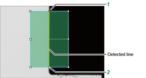
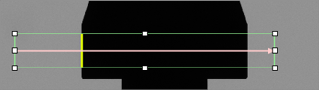
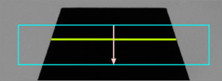
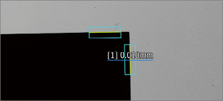
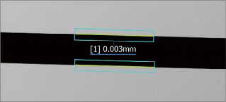
Creating lines and a measurement area
Click the 1st point.
Click the 2nd point.
A straight line is detected automatically.
If a straight line cannot be detected, the detected area turns red.
Clicking the detected area and operating , , or enables the area to be adjusted.
Adjusting the detection area automatically detects straight lines in that area.
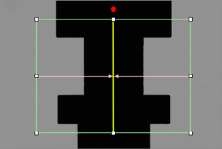
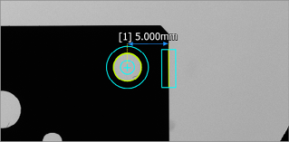
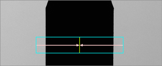
Creating points
Click the starting point.
Click the ending point.
A point is detected automatically.
If a point cannot be detected, the detected line turns red.
Moving the detected line automatically detects points on the detected line after it is moved.
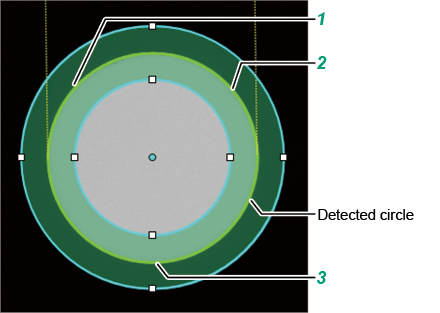
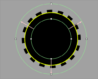
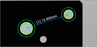
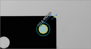
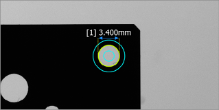
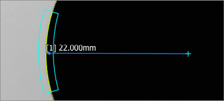
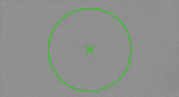
Creating a circle/arc
Click the 1st point.
Click the 2nd point.
Click the 3rd point.
A circle/arc is detected automatically.
If a circle/arc cannot be detected, the detected area turns red.
Clicking the detected area and operating enables the area to be adjusted.
Adjusting the detection area automatically detects circles/arcs in that area.
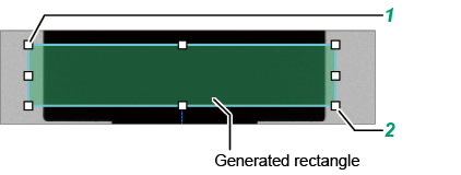
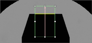
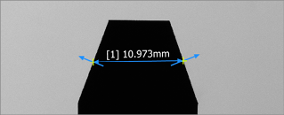
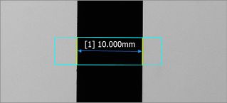
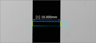
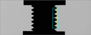
Measuring an area by specifying a rectangle (Master Difference (Area/Contour), Area, Contour Extraction, Profile)
Click the 1st point.
Click the 2nd point.
A rectangle is automatically generated and lines and points are detected automatically.
If points or lines cannot be detected inside the rectangle, the detected area turns red.
Clicking the detected area and operating or enables the area to be adjusted.
Adjusting the detection area automatically detects points and lines in that area.
Convenient Operation of the Tool Settings
Selecting an element
Other than selecting an element directly on the main screen, use one of the methods below to select an element.
This operation is application to tools to be set with a combination of multiple elements.
Select from a list (when creating a new element)
Selecting [Select from List] displays a list of set elements.
Placing the mouse pointer over an element highlights the applicable element on the main screen.
Select the element to be set and click [Next].
Reselect from a list (when editing an element)
To edit a set tool, selecting displays the specified element name.
Selecting an element name displays a list of set elements.
Placing the mouse pointer over an element highlights the applicable element on the main screen.
Select the element to be set and click [Next].
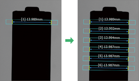
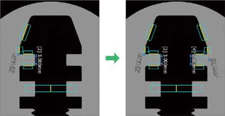
Multiple Copy
Using [Multiple Copy] on the [Edit] menu enables the selected detection area and measurement tool to be copied with the specified direction (vertical/horizontal, rotation), quantity, and interval (distance, angle).
Inverted Copy
Using [Inverted Copy] on the [Edit] menu enables the selected detection area and measurement tool to be copied inversely on the specified axis.
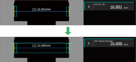
Replace with Diameter Tool
Using [Replace with Diameter Tool] in the [Edit] menu enables [LN - LN] to be replaced with [Diameter].
For two head configurations, [LN - LN] set across Head A and Head B cannot be replaced with [Diameter].
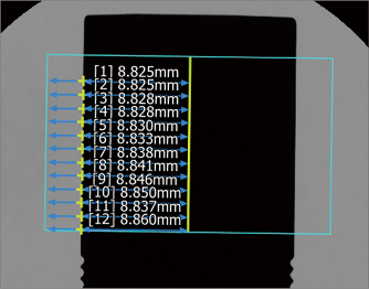
Bulk Operation (LN - PT)
Measures the distance between a line and multiple points at the same time.
The measurement result is the same as when setting [LN - PT] on multiple places. The setting of lines individually can be omitted.
The [LN - PT] detection conditions ([Tolerance Settings], [Moving Average], [Processing Settings]) can also be batch set.
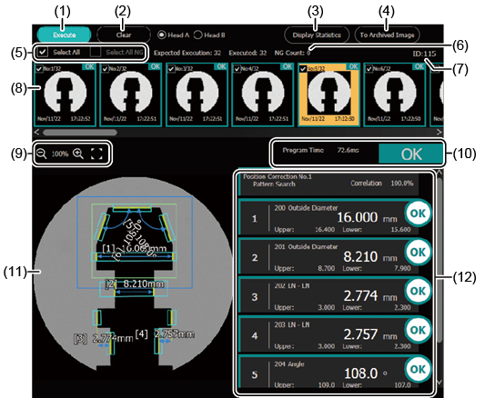
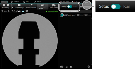
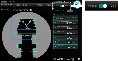
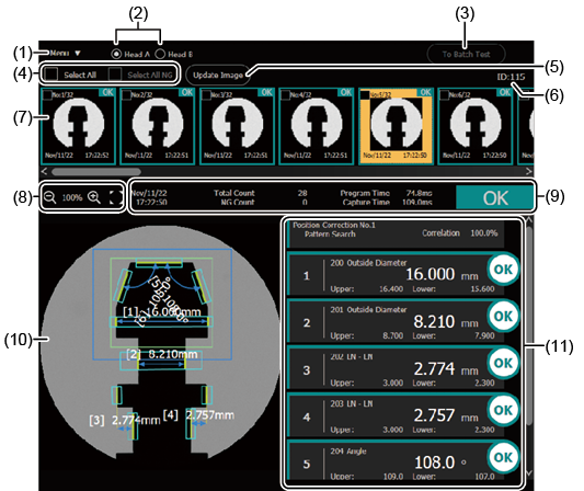
Layout of the Screen
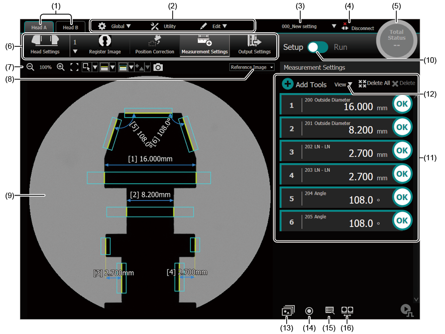
[Setup] Mode
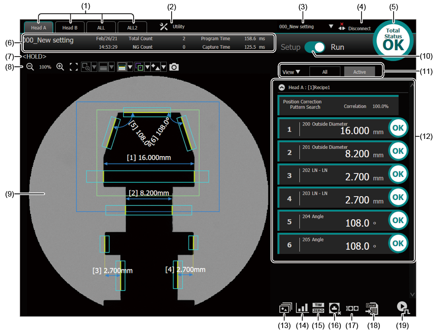
Head Display
Displays the settings for the applicable head.
If two heads are connected, selecting a tab enables the settings to be changed to the applicable head.
If only Head A is connected, the [Head B] tab will not be displayed.
Changes the display magnification of the main screen.
Fits the entire view to the main screen.
or
Toggles between [Rectangular Zoom] and [Element Select].
or
Toggles between [Show Edge Point Trail] or [Show Fitting Lines].
or
Shows or hides the area.
or
Changes the resolution of the main screen.
Saves the displayed screen to the following location in JPEG format.
SD2:\tm-x\capture\
Image type
Displays the type of image (Reference Image/Image Display/Archived Image) that is being displayed on the main screen. Additionally, this option can be used to change the image type displayed on the main screen.
The settings for any image type can be changed on the measurement settings screen.
When [Image Display] has been selected, the imaging file can be saved by right-clicking on the main screen.
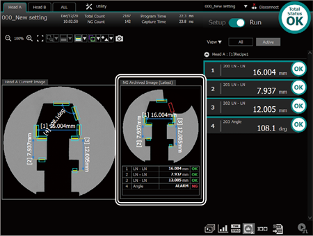
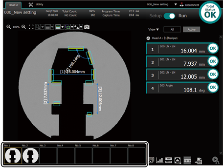
When [Archived Image] has been selected, the measurement results for an image accumulated from “Archived Image (13)” can be checked by selecting that image.
Main screen
Displays the reference image registered in the measurement settings, measurement tools, and measurement results.
The following can be performed via the right-click menu.
Saving the imaging file (images that can be used in the simulator)
Capturing the screen (full screen capture)
Files saved by [Save the Imaging File] can be used in the simulator.
When saving a file with a dedicated monitor, the file is saved to SD card (SD2 slot).
When saving a file with TM-X Navigator, the file is saved to the folder in the PC.
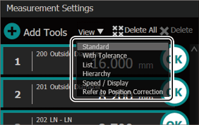
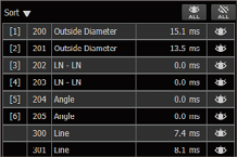
Select the display method of the tool list. Selecting [All] displays all the tools set for the Program. Selecting [Active] only displays the recipe tools currently active.
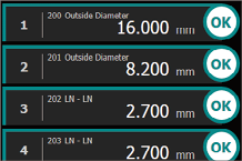
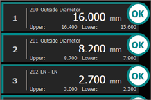
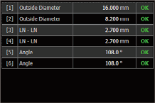
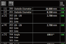
Tools List
Displays the measured values and judgment results for the tools set for the Program.
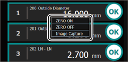
a
Right-clicking the tool name enables [ZERO ON] and [ZERO OFF] to be performed.
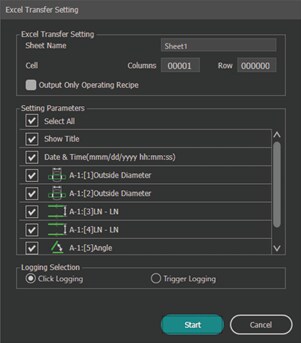
Measurement Result Output supports Microsoft Excel 2016 or later.
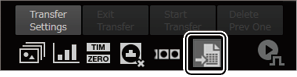
Transfer settings/start
Configure the settings to send measurement results to Excel and then start the transfer to Excel.
Set the destination sheet name, write start cell, items to be transferred, and function selection (timing data is to be sent).
Selecting [Output Only Operating Recipe] exports only the items set for the recipe in operation to Excel irrespective of whether any of the items to be transferred are selected.
Exit transfer
Ends the transfer of the measurement results to Excel.
Start Transfer
Enabled when [Click Logging] is selected for [Logging Selection].
Measurement results (one time) are sent to Excel based on the transfer settings.
Delete Prev One
The most recently sent measurement results are deleted from Excel.
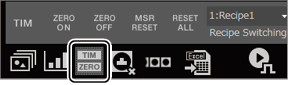
Trigger
When [External Trigger] is set for [Trigger Mode] in the head settings, a trigger is issued every time the button is pressed.
Program Settings Menu
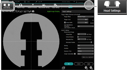
Head Settings
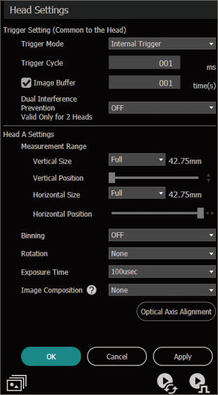
Trigger Setting
Trigger Mode
Specify the type of the trigger signal.
Internal Trigger
Generates a trigger automatically and continuously inside the controller to measure.
External Trigger
Measures by inputting a trigger at the desired timing from an external source (terminal, command, or mouse).
Trigger Multiple Times
Can be set when [External Trigger] is selected for the [Trigger Mode].
When this setting is selected, a specified number of imaging triggers are issued internally by a single external trigger input.
Measurement processing is performed for each image taken and the measurement value is determined by the processing specified in [Hold mode] of the measurement tool.
Count
Specifies the number of imaging triggers to issue internally when the external trigger is received.
Cycle
Specifies the number of imaging triggers to issue internally.
Images are captured with an imaging trigger issued after capture is enabled.
To capture images at the shortest interval, set to 0 ms.
If [Trigger Multiple Times] is selected, the moving average for the measurement tool cannot be used.
Trigger Cycle
Can be set when [Internal Trigger] is selected for the [Trigger Mode].
Sets the internal trigger interval.
Trigger Delay
Can be set when [External Trigger] is selected for the trigger mode.
Specifies the delay time when delaying the start of image capture after trigger input.
Image Buffer
Select this option to capture the next image without waiting for measurement processing of the previously captured image.
Dual Interference Prevention
Prevents light that reflects off the target emitted from the transmitter head of Head A (B) affecting (dual interference) measurements due to that light entering the receiver head of Head B (A) when using two connected heads because of the positional relationship of Head A and Head B by shifting the capture timing of Head A and Head B.
Head A (B) Settings
Head B settings are displayed when two heads are connected.
When using one head, use HEAD-A connector.
Measurement Ranges
Set the range to capture images.
Compressing the measurement range (vertical and horizontal sizes) enables the time taken to capture images to be reduced.
Moving the sliders for [Horizontal Position] and [Vertical Position] changes the measurement range.
Binning
Set to ON to speed up image transfer.
Doing so will pixelate the transferred images.
Rotation
Set to rotate the captured image.
Rotated images can be displayed, measured, and output.
This is useful when the head has been rotated and then installed.
If [Head-to-head Adjustment Setting] is [Use], [Rotation] cannot be set.
Exposure Time
Select the exposure time (100 µs (default value), 50 µs, 25 µs).
Shortening the exposure time reduces the light intensity, but enables blurring to be decreased when a moving object is captured.
Image Composition
Multiple images are captured for one trigger and image composition processing (None/Average/Dark Composition/Bright Composition) is performed.
Average
Images are captured with the specified count for one trigger and the averaged images are sent to the controller.
Dark Composition
Bright Composition
Images are captured with the specified count and cycle for one trigger and the processed image (images composed from the darkest and brightest elements) are sent to the controller.
Setting [Image Composition] increases the capture time.
One image is always sent from the head to the controller. Setting [Image Composition] sends only the image for which image composition was performed.
If the average frequency differs between Head A and Head B, measurement is performed once averaging is complete on the head with the greater frequency.
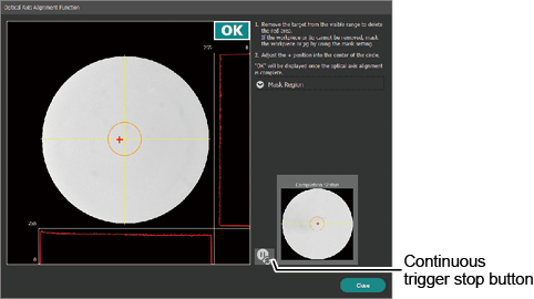
Optical Axis Alignment
Align the optical axes of the transmitter head and receiver head.
Follow the on-screen instructions to adjust the transmitter head and receiver head positions.
When a target or a jig can be seen in the measurement range, optical axis alignment can still be done by using the [Mask Region].
When half or more of the field of view is covered by the mask, OK/NG judgment may become unstable.
Since setting a mask region with a dedicated display slows down this function, it is recommended to temporarily stop updating the image while the optical axis alignment is being performed.
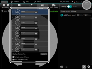
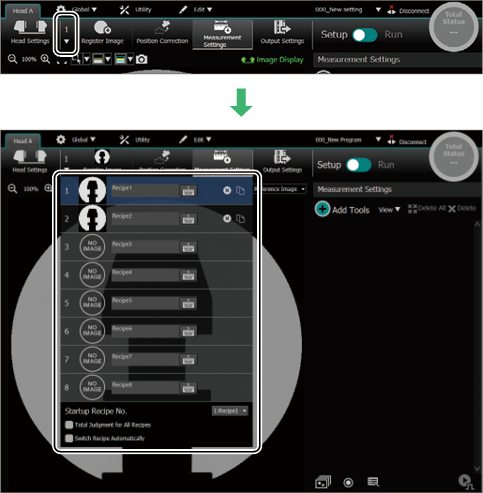
Selecting a Recipe
Eight recipes can be set for one Program.
A reference image, position correction, and measurement settings can be saved for each recipe.
Recipe 1 to 8
Select the recipe to be configured.
If a reference image is registered, a thumbnail image will appear.
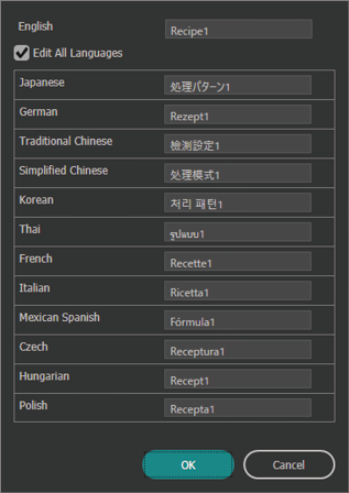
Name
Clicking the keyboard icon enables the recipe name to be configured.
Recipe initialization
Clicking on the right of the list displays a confirmation screen.
Clicking [OK] enables the recipe to be initialized.
Copy Recipe
This function copies the settings of an existing recipe and pastes them into another recipe.
Specify the source and destination for the recipe number, and then copy the recipe.
If two heads are connected, the recipes for both heads are copied.
Startup Recipe No.
Select the recipe number to be used when the controller starts.
Total Judgment for All Recipes
If multiple recipes are set for one Program, they can be judged as a group.
Switch Recipes Automatically
If multiple recipes are registered, [Recipe] can automatically be changed in accordance with the captured images of the target.
In [Run] mode, the recipe can be changed by a command or with [Measurement Control Bar].
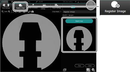
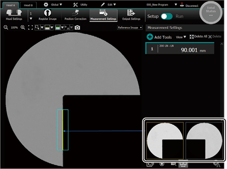
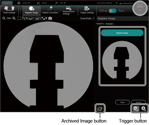
Register Reference Image
Place the target and then register the reference image
Check the target position displayed on the main screen with the [Trigger] or [Continuous Trigger] or [Archived Image] button, and then click the [Register Image] button.
To register a reference image for Head B, select the [Head B] tab first.
If [2 Head Switching] (Detail)is selected, the reference images of Head A and B can be simultaneously registered.
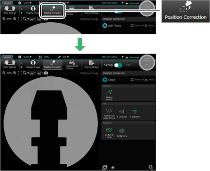
Position Correction
This function adjusts position misalignment or tilt of a target against the reference image.
Even if differences in target positioning (position and angle misalignment) occur, the desired measurement areas can be measured stably.
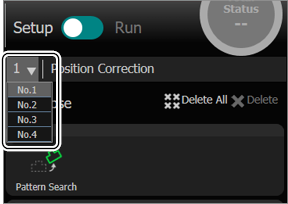
Up to four position correction groups (Nos. 1 to 4) can be set for one processing pattern.
To set a position correction, the [Register image] is required.
Select the position adjustment group number and then set the tool.
Select the position adjustment group number for [Position Correction] in [Specify Region] for the measurement tool.
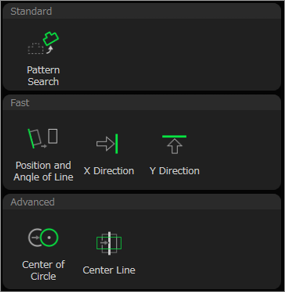
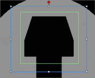
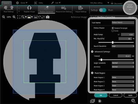
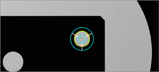
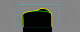
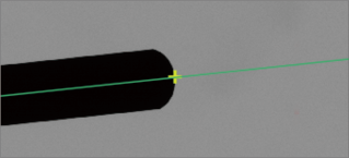
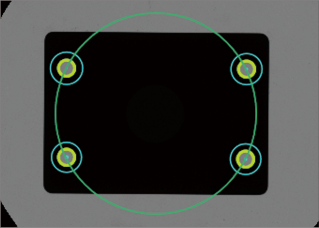
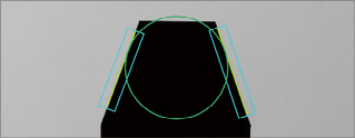
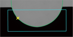
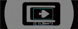
Shapes that are similar to the target are searched for in the pattern region (green frame) and position adjustment is then performed.
A pattern search is performed inside the search region (blue frame).
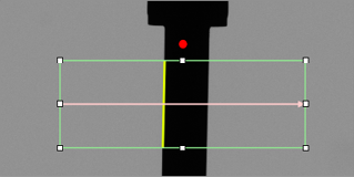
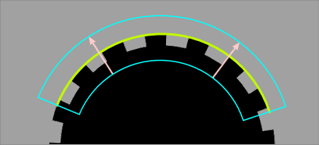
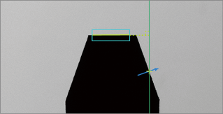
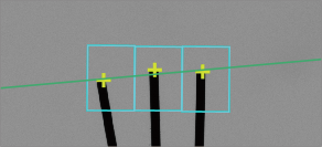
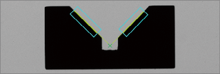
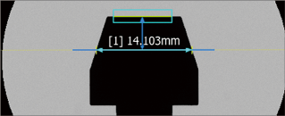
Multiple edges in the line detection area (green frame) are detected to find a line from information about the edges of the detected points. Position adjustment is performed based on the position of the found lines and angle formed by the horizontal axis and that line.
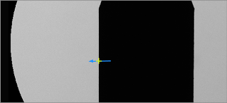
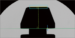
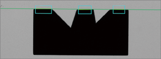
Edges (X direction) inside the edge detection area (green frame) are detected and position adjustment is performed.
Edges (Y direction) inside the edge detection area (green frame) are detected and position adjustment is performed.
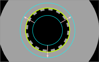
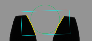
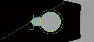
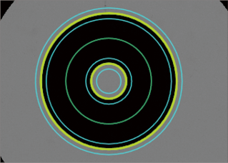
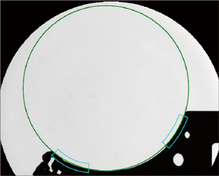
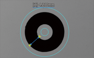
Multiple edges in the circle detection area (green frame) are detected to find the center of the circle from information about the edges of the detected points. Position adjustment is performed based on the center of the circle.
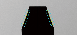
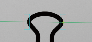
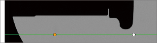
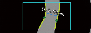
Multiple edges in the line detection area (green frame) are detected to find the center of the line from information about the edges of the detected points and position adjustment is performed. Position adjustment can be performed in the center of the target for targets that have a varying thickness.
Detection conditions for [Position Correction]
This section describes the detection conditions for [Position Correction].
The items that can be set differ depending on the tool.
1
Tool Name
2
Pattern Region
(Rotated Rectangle/Circle)
3
Angle Range
4
Min. Match (%)
5
Search Sensitivity
6
Advanced Settings
7
Scan Direction
8
Edge Direction
9
Correction Method
10
Remove Defects
11
Advanced Edge Settings
12
Mask Region
1. Tool Name
Set the desired tool name.
2. Pattern Region (Rotated Rectangle/Circle)
Select the shape of the pattern region.
3. Angle Range
Specify the angle range by +/- for pattern search where the measurement target is tilted.
Setting a large angle increases the amount of computing. Hence, measurement time increases.
4. Min. Match (%)
This figure indicates how similar the pattern image (green frame) and measurement image are in the search region (blue frame).
Measurement is only performed when the search results exceed the minimum match value.
5. Search Sensitivity
Changes the compression rate of an image when searching to specify the priority between the search speed and stability.
[Low] prioritizes the search speed and [High] prioritizes stability.
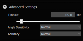
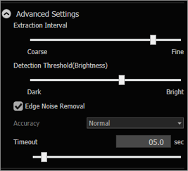
6. Advanced Settings
Timeout
Sets the maximum time from the start to the finish of pattern search.
Angle sensitivity
Changes the angle step width when searching and specifies the priority of stability and speed of the rotation direction.
[Low] prioritizes the search speed and [High] prioritizes stability and accuracy of the rotating direction.
Accuracy
Specifies the search accuracy when searching.
[Low] prioritizes the search speed and [High] prioritizes accuracy.
7. Scan Direction
Select a direction to detect edges. The direction is indicated by the orientation of the pink arrow on the main screen.
Position and Angle of Line / X Direction / Y Direction
Select either [Forward] (the direction of the pink arrow) or [Reverse].
Center of Circle
Select [Out → Center] or [Center → Out].
8. Edge Direction
To detect edges that change from dark to light or light to dark, select [Both], [Light to Dark], or [Dark to Light].
9. Correction Method
Set a method to adjust edges when performing position adjustment.
FAR
Use the furthest edge in the direction of the pink arrow inside the detection area as the adjustment reference.
NEAR
Use the closest edge in the direction of the pink arrow inside the detection area as the adjustment reference.
Average
Use the average value of the X-Position (or Y-Position) on the edge in the detection area as the position adjustment reference.
Fast
Compress and detect the image inside the detection area in the detection and perpendicular directions to speed up adjustment.
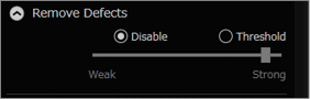
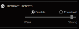
10. Remove Defects
Remove edge points that are away from the edge point trail as abnormal points when calculating fitting lines. Errors may occur due to the effects of burrs or contamination on the measurement target.
Setting the slider to the [Strong] side judges small gaps as abnormal points.
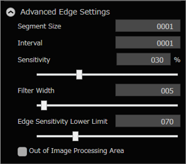
11. Advanced Edge Settings
Segment size (line position and angle/circle center/center line)
Specify the segment size in which an edge is detected.
Enlarging the segment size will degrade the detection sensitivity. However, the result is less affected by noise.
Interval (Position and Angle of Line/Center of Circle/Center Line)
Specify the segment size in which an interval is detected.
Sensitivity
Set the criteria for recognition of contrast above a certain percentage as an edge where the contrast variation is most remarkable (100%).
As edges below this edge sensitivity are not recognized, use this setting to ignore noise.
Filter Width
When a noise component causes false edge detections, increasing the filter width can reduce the false detections.
Edge Sensitivity Lower Limit
Set the lower limit for edge detection. Edges below the lower limit are not detected.
Out of Image Processing Area
This processing is performed when the position adjustment tool area is outside the range of the loaded image. Select the check box to speed up processing (processing is not performed outside of the area).
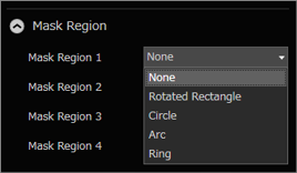
12. Mask Region
Up to four areas to exclude (mask regions) in the position adjustment area can be specified.
This is useful when the target has a complicated shape or when an area needs to be excluded from the measurement.
For the [Pattern Search] tool, select [Pattern Area Mask] to set a mask for the pattern area, or [Search Area Mask] to set a mask for the search area.
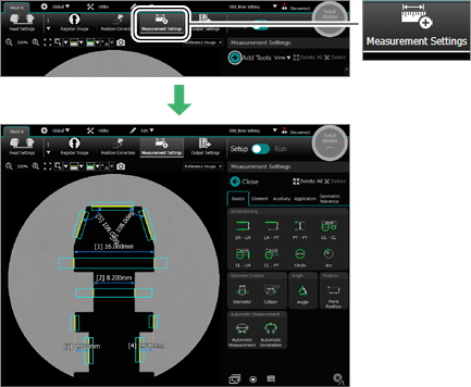
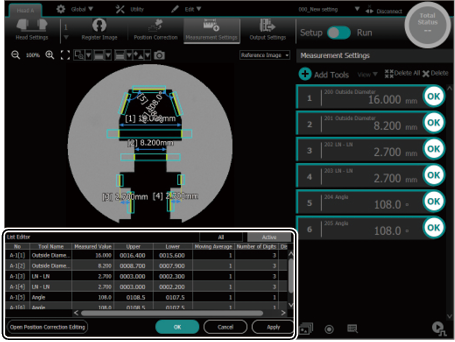
Measurement Settings
Set the tool to measure the target.
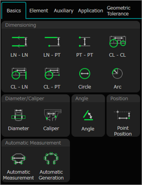
Basics
A sequential workflow from the edge (element) detection settings necessary for measurement to the display of the measurement results can be set.
Measurement settings used for edges (elements) that have already been detected are also used.
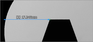
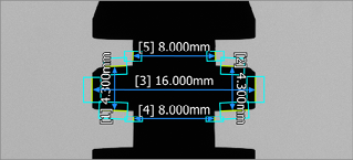
Dimensioning
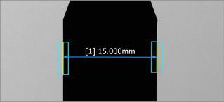
Measure the distance between two lines.
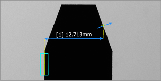
Measure the distance between a line and a point.
Measure the distance between two points.
Measure the distance between two circles (or arcs).
Measure the distance between a circle (or arc) and a line.
Measure the distance between a circle (or arc) and a point.
Measure the diameter or radius of a circle.
Measure the radius of an arc.
Diameter/Caliper
Measure the outside diameter of a target with a cylindrical shape.
A value that adjusted the end surface reflection characteristic of the cylindrical shape will be output.
Detect the edges in the specified area and measure the distance between edges (distance between the caliper jaws).
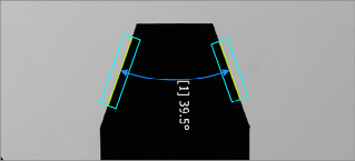
Angle
Measure the angle between two lines.
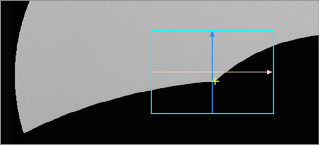
Position
Measures the coordinates with the origin on the left side of the screen.
Automatic Measurement
Automatically detect edges in the specified area and measure the distance between the edges.
Automatically detect edges in the specified area. Selecting any two of the detected edges measures the distance or angle between them.
When the angle between the edges is 5° or less, the distance is measured. If not, the angle is measured.
Element
Detect the elements to be used for the measurement of points, lines, and other features.
Line/Circle
Detect lines.
Detect peak lines that go through peak points detected from the inside of the specified rectangular area.
Detect the center line between edges.
Detect lines of the specified width parallel to the specified rectangular area.
Detect circles.
Detect arcs.
Detect peak circles that go through peak points detected from the inside of the specified circular area.
Detect peak arcs that go through peak points detected from the inside of the specified arc area.
Point
Detect points on the set line.
Max/Min point
Detect the maximum or minimum point inside the rectangular area.
Detect the maximum or minimum point in the circle or arc area.
Inflection
Extract points for which the changes in the line of the extracted edge point trail are above are certain level.
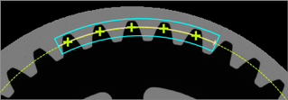
Pitch Element
Detect an edge point on a line.
Detect an edge point on the circumference.
Pitch Element (Angle)
Detect the elements to measure the pitch angle of the edges on a line.
Detect the elements to measure the pitch angle of the edges on the circumference.
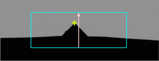
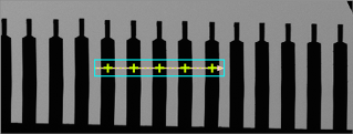
Tip
Detect tips at the apex from the inside of the specified rectangular area.
Defect Element
Detect a foreign object of an indeterminate form that has adhered to the target compared to the shape (rotated rectangle, circle, or arc) extracted from the reference image.
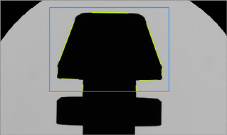
Contour
Automatically detect the target’s edge and extract a group of contour points from that edge.
Others
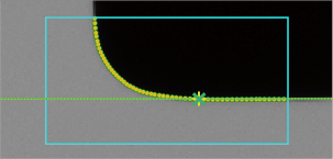
Detects the specified circle diameter tangent to the contour inside the specified area.
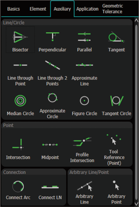
Auxiliary
Detect the elements to be used for the measurement of points, lines, and other features.
Auxiliary cannot be created if no lines (straight line, circle, or arc) or points are shown on the main screen.
Before creating an auxiliary, measure the target with [Basics] or use [Element] to create a line, circle, or point on the main screen.
Line/Circle
Draw a median line from two selected lines, circles or points.
Draw a perpendicular line that goes through the selected point on the selected line.
Draw a parallel line at the specified distance or that goes through the selected point on the selected line.
Draw a line that connects the two selected circles (arcs) or a point and the circle (arc).
Draw a line that passes through the selected points.
Draw a line that goes through the two selected points.
Draw the approximate line that passes through the selected points.
Draw a median circle from two selected circles or arcs.
Draw the approximate circle that passes through the selected points.
Draw a circle that passes through the selected point with the selected point in the center or a circle with the specified radius.
Draw a circle connecting to two selected lines.
Point
Draw the intersection of the two selected lines (straight lines, circles or arcs).
Draw the midpoint between the two selected points.
Use the Contour Extraction Tool to draw the intersection points of the extracted contour, line and circle/arc.
Use the OBD element to detect the contact points of the circle and create points.
Connection
Create a circle by combining two or more selected arcs.
Create a line by combining two or more selected lines.
Arbitrary Line/Point
Draw a line that goes through any two selected points.
Create a point at any selected position.
Application
These are various tools that facilitate complicated measurement.
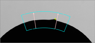
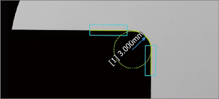
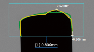
Corner
Measure the corner arc based on the two lines that form a corner.
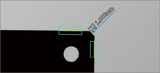
Measure the chamfer surface from the two lines that form a chamfer surface.
Master Difference
Measure the target area inside the specified area and calculate the differences to the reference image.
Measure the target’s contour inside the specified area and calculate the differences from the reference image.
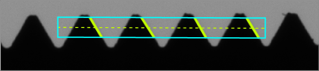
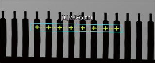
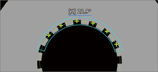
Pitch Measurement
Measure the pitch (line) distance of the edges on the line or circumference.
Measure the pitch angle of the edges on the line or circumference.
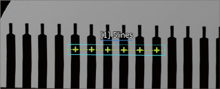
Count
Count the number of pitches between edges for the specified pitch element tool.
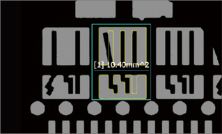
Area
Measure the area of the target inside the specified area.
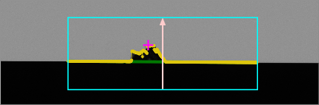
Defect
Detect locations that deviate from the reference line calculated from the edge information and then measure that distance.
Gap
Measure whether there is a gap in any specified area.
If there are multiple gaps, the shortest distance between gaps can be measured by selecting [Stable] for [Processing Mode].
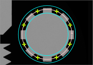
Thickness
Measure the ring thickness at the specified interval. The average value or the maximum and/or minimum values(s) can be output.
Advanced
Measure the distance between edges from any specified lines.
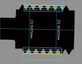
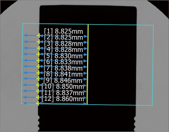
Thread
Measure the effective, outside or minor diameters of a target in the shape of a thread.
Bulk Operation
Measures the distance between one line and multiple points at the same time.
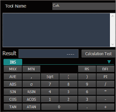
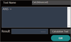
Calculation
Use the measurement result and calculate.
The calculation results from other calculation tools can be inserted into the formula.
There is no compatibility between [Standard] and [Advanced]. Copying the content from one to the other cannot obtain an correct calculation result.
Standard
Advanced
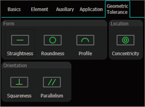
Geometric Tolerance
Straightness and perpendicularity can be measured.
Form
Measures the straightness of the specified line.
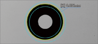
Measures the circularity of the specified circle or arc.
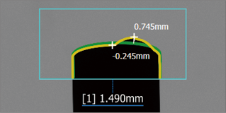
Measure the contour of the specified target range.
Location
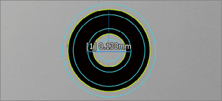
Measure the concentricity of the two specified circles or arcs.
Orientation
Measure the perpendicularity of the specified line against the reference line.
Measure the parallelism of the specified line against the reference line.
Detection conditions for measurement settings
This section describes the detection conditions for [Measurement Settings].
The items that can be set differ depending on the tool.
Basics
Dimensioning
Diameter/Caliper
Angle
Position
Automatic measurement
1
Tool Name
2
Angle Range
3
Measurement Pattern
4
Base Measurement Direction
5
Diameter/Radius
6
Detection Conditions
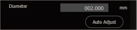
7
Auto Adjust
8
Edge Direction
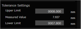
10
Tolerance Settings
11
Moving Average
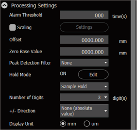
12
Processing Settings
13
Remove Defects
15
Remove Isolated Point
16
Advanced Edge Settings
17
Specify Region
18
Mask Region
19
Width Measurement
20
Detect Edge
21
Delete Edge
Element
Line/Circle
Point
Max/Min point
Inflection
1
Tool Name
7
Auto Adjust
8
Edge Direction
13
Remove Defects
14
Remove Isolated Point
15
Gauge Line
16
Advanced Edge Settings
17
Specify Region
18
Mask Region
22
Output Ppattern
23
Scan Direction
24
Correction Method
25
Shape
26
Detection sensitivity, Lower Limit of Detection Threshold, Upper Limit of Detection Threshold
27
Display Color Settings
Element (Cont.)
Pitch Element (Distance)
Pitch Element (Angle)
Tip
Defect element
Contour
Others
1
Tool Name
7
Auto Adjust
8
Edge Direction
9
Diameter
13
Remove Defects
16
Advanced Edge Settings
17
Specify Region
18
Mask Region
23
Scan Direction
27
Display Color Settings
28
Reference Line
29
Pitch pattern settings
30
Pitch Interval Value
31
Half Angle
32
Maximum Permissible Feature Count
33
Set ALARM as the result when straight line detection fails
34
Defect Detection Conditions
35
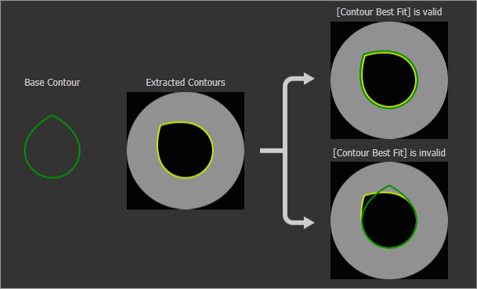
Contour Best Fit
36
Minimum detect size
37
Advanced Settings
57
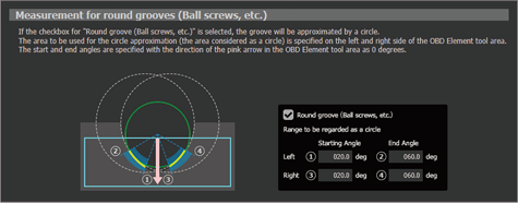
Round groove (Ball screws, etc.)
Auxiliary
Line/Circle
1
Tool Name
3
Measurement Pattern
22
Output Pattern
27
Display Color Settings
37
Distance from Base Elements
39
Degrees of Rotation
40
Radius
41
Pattern to Create
Auxiliary (Cont.)
Point
Connection
Arbitrary line/Point
1
Tool Name
8
Edge Direction
22
Output Pattern
23
Scan Direction
27
Display Color Settings
41
Pattern to Create
42
Point 1/Point 2
43
Point
55
Specify Detected Point
Application
Corner
Master Difference
Pitch Measurement
Count
Area
Defect
Gap
Thickness
Width of specific position
Thread
Bulk Operation
Calculation
1
Tool Name
3
Measurement Pattern
6
Detection Conditions
7
Auto Adjust
8
Edge Direction
10
Tolerance Settings
11
Moving Average
12
Processing Settings
13
Remove Defects
16
Advanced Edge Settings
17
Specify Region
18
Mask Region
35
Contour Best Fit
36
Minimum Detect Size
44
Measurement Type
45
Items to be Judged for Tolerance
46
Sensitivity
47
Dead Band
48
Distance from Reference
49
Measurement Method
50
Exclusion Area Settings
51
Abnormal Segment Tolerance
52
Measurement Item
53
Setting the reference axis
54
Display the detection point only when NG.
56
Processing Mode
Geometric tolerance
Form
Location
Orientation
1
Tool Name
10
Tolerance Settings
11
Moving Average
12
Processing Settings
35
Contour Best Fit
36
Minimum detect size
54
Display the detection point only when NG.
1. Tool Name
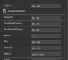
Set the tool name.
Selecting [Edit All Languages] enables the tool name to be edited in different languages.
2. Angle Range
Select the measurement range for the angle.
([360 deg Display] or [+/- 90 deg Display])
3: Measurement Pattern
Select the measurement pattern.
Selecting measurement patterns updates the measurement values on the main screen.
CL - CL / CL - LN
Select [Between Centers], [Maximum], or [Minimum].
CL - PT
Select [Center], [Maximum], or [Minimum].
Angle
Select [Normal], [Supplement], [Complementary Angle 1], or [Complementary Angle 2].
Bisector
Select [Forward] or [Reverse].
Area
Select [Black] or [White].
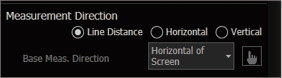
4. Base Measurement Direction
Select the measurement direction.
PT - PT/CL - PT
Line Distance
Measure the distance between points or a point and the center of a circle.
Horizontal *
Measure the distance between points or a point and the center of a circle in parallel with the item selected in [Base Measurement Direction].
Vertical *
Measure the distance between points or a point and the center of a circle in the vertical direction with the item selected in [Base Measurement Direction].
* If a line is set, clicking specifies the reference line on the main screen.
CL - CL
Center Distance
Measure the distance between the center of circles.
Horizontal *
Measure the distance between the center of a circle in parallel with the item selected in [Base Measurement Direction].
Vertical *
Measure the distance between the center of a circle in the vertical direction with the item selected in [Base Measurement Direction].
* If a line is set, clicking specifies the reference line on the main screen.
Point Position
Select whether to use the X- or Y-Position of the specified point.
5. Diameter/Radius
Circle/Arc
Select whether to output the diameter or radius.
6. Detection Conditions
Circle
Select [Max.], [Min.], [Fitting], [Inscribed], or [Circumscribed].
Maximum
Set “Center of circle found with fitting” as the center based on the detected edge and detect the circle that passes through the furthest edge point from that center.
Minimum
Set “Center of circle found with fitting” as the center based on the detected edge and detect the circle that passes through the closest edge point from that center.
Fitting
Detect a proximate circle using the least square method from the detected edge.
Inscribed
Detects an inscribed circle from the detected edge.
Circumscribed
Detects a circumscribed circle from the detected edge.
The center when [Maximum] or [Minimum] is selected is the same as the center when [Fitting] is selected.
The circle detected in [Fitting] and the center of the circle detected in [Inscribed] and [Circumscribed] may not match.
If [Inscribed] or [Circumscribed] are selected, the processing speed will be slower than if [Fitting], [Maximum], or [Minimum] was selected.
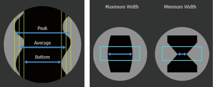
Diameter
Select how to measure two detected edges.
Average
Detect two proximate lines using the least square method based on the detected edge. Detect the distance between the center of those lines.
Peak
Detect two proximate lines using the least square method based on the detected edge. The lines are tilted and the distance between the center of the two lines that go through the edge for the outermost lines (furthest point) is detected.
Bottom
Detect two proximate lines using the least square method based on the detected edge. The lines are tilted and the distance between the center of the two lines that go through the edge for the innermost lines (closest point) is detected.
Maximum Width
Detects the distance of the maximum width based on the detected edge.
Minimum Width
Detects the distance of the minimum width based on the detected edge.
The tilt of the lines when [Peak] or [Bottom] is selected is the same as the tilt of the lines when [Ave] is selected.
Ring Thickness
Select [Maximum Width], [Minimum Width], or [Average].
Maximum Width
Measure the ring thickness of the measurement target at the interval specified in [Interval] for [Advanced Edge Setting] to detect the maximum value.
Minimum Width
Measure the ring thickness of the measurement target at the interval specified in [Interval] for [Advanced Edge Setting] to detect the minimum value.
Average
Measure the ring thickness of the measurement target at the interval specified in [Interval] for [Advanced Edge Setting] to detect the average values.
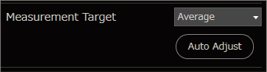
7. Auto Adjust
Automatically adjust the tool area and edge detection conditions.
8. Edge Direction
Caliper
Select [Light->Dark] or [Dark->Light] for the edge direction.
Line, Peak Line, Center Line, Circle, Arc, Peak Circle, Peak Arc, Point, Max/Min Point (Rectangle), Max/Min Point (Arc), Tip, Defect Element, Corner Arc, Gap
Select whether to detect edges that change from dark to light or light to dark.
If the [Scan Direction] and [Edge Direction] have not been appropriately combined, the edge may not be detectable.
9. Diameter
Specify the diameter of the circle used in the [OBD Element] tool with a numeric value.
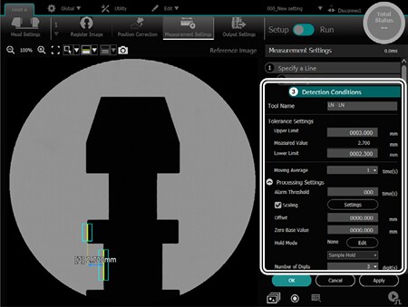
10. Tolerance Settings
Set the tolerance to judge the measured value ([Upper Limit] and [Lower Limit]).
11. Moving Average
Set the count to average the measured values.
12. Processing Settings
Alarm Threshold
Specify the measurement count to hold the valid data until just before measurement becomes invalid.
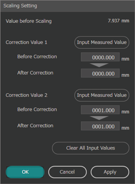
Scaling
Scaling is the process of setting a display value for the desired measured value and correcting any difference between the measured value and the display value. A display value is set for the two measured values.
The measured value obtained before adjustment when [Input Measured Value] was clicked can be assigned to [Correction Value 1] and [Correction Value 2].
Offset
Add/subtract any value from the display value.
Offset processing is performed on a value after measurement mode processing, auto zero processing, and scaling is performed.
Zero Base Value
Specify the value to subtract from the measured value with “Auto zero processing” when ZERO ON is input. The setting value is automatically written to “finalized measured value” when ZERO ON is input.
If the hold value is “10” when the standard value is “10,” the measured value becomes “0.”
Peak Detection Filter
Sets the peak detection filter.
Selecting [Hold Peak Value] or [Hold Bottom Value] enables [Level] and [Hysteresis] to be set.
If [Peak Detection Filter] is set, [Nearest Hold] and [Other Tool Reference Hold] cannot be selected in [Hold Mode].
Hold Mode
Set whether to continue sampling during measurement or specify a sampling period and measure the maximum or minimum value.
Peak Hold
Measure the maximum value in the specified period.
Bottom Hold
Measure the minimum value in the specified period.
Peak to Peak Hold
Measure the “maximum value - minimum value” in the specified period.
Average Hold
Measure the average value in the specified period.
Sample Hold
Measure the value at the specified moment.
Nearest Hold
Measures the value that is closest to the specified value within the specified period.
Other Tool Reference Hold
The value when the reference measurement tool is at its maximum or minimum is the measured value within the specified period.
Number of Digits
Set the number of decimal points for the measured value.
+/- Direction
Select [None (absolute value)], [Forward], or [Reverse Direction] for the sign of the measured value.
This item can be set for [LN - LN], [LN - PT], [PT - PT], [CL - CL], [CL - LN], and [CL - PT].
The left side is the plus direction for the direction of the base line (the element selected first when setting a tool).
[None (absolute value)] is set for a measurement element for which there is no line direction such as [Center Distance].
Display Unit
Select the unit to be displayed on the main screen.
[Display Unit] is not shown if an angle, area, number of pitches, and master difference (area) have been set.
Enable DIA correction
Enabling this setting outputs a value that adjusted the end surface reflection characteristic of the cylindrical shape.
This item can be set for [Outer diameter].
13. Remove Defects
Remove edge points that are away from the edge point trail as abnormal points when calculating fitting lines. Errors may occur due to the effects of burrs or contamination on the measurement target.
Setting the slider to the [Strong] side judges small gaps as abnormal points.
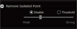
14. Remove Isolated Point
Set a threshold value to remove edge points in an isolated position from edge extraction.
Setting the slider to the [Strong] side judges small gaps as isolated points.
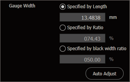
15. Gauge Width
Set how to calculate the specified line and the value in the [Gauge Line] tool.
Specified by Length
Specify the segment length with a number.
Specified by Ratio
Specify the ratio of the black width for the area.
Specified by black width ratio
The average of the monochrome ratio of the respective crests can be specified as the gauge line can be detected across more than black and white pairs.
The monochrome ratio is calculated by the formula: black width/(black width + white width).
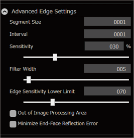
16. Advanced Edge Settings
LN - LN
Clear this check box to disable [Keep the Line Parallel].
For details of “Keep the Line Parallel”, refer to “Technical Descriptions”.
Diameter, Caliper, Line, Peak Line, Center Line, Gauge Line, Circle, Arc, Peak Circle, Peak Arc, Point, Max/Min Point (Rectangle), Max/Min Point (Arc), Inflection, Tip, Defect Element, OBD Element, Pitch Element (Distance), Pitch Element (Angle), Area, Width of Specific Position, Gap, Ring Thickness
Segment Size
Specify the segment size in which an edge is detected.
Enlarging the segment size will degrade the detection sensitivity. However, the result is less affected by noise.
Interval
Specify the segment interval. Increasing the segment interval omits processing points, which shortens measurement time.
Sensitivity
Set the criteria for recognition of contrast above a certain percentage as an edge where the contrast variation is most pronounced (100%).
As edges of contrast below this edge sensitivity are not recognized use this setting to ignore noises.
Filter Width
To detect minute items like narrow lines, decrease the filter width. Additionally, when noise causes false edge detections, increasing the filter width can reduce the false detections.
Edge Sensitivity Lower Limit
Set the lower limit for edge detection. Edges below the lower limit are not detected.
Out of Image Processing Area
This processing is performed when the various tool areas are outside the range of the loaded image. Select the check box to speed up processing (processing is not performed outside of the area).
Minimize End-Face Reflection Error
Select this check box to decrease the effects of end surface reflection from targets that have a parallel depth in the light emission direction.
There are no segment size, interval, or out of image settings for the “Pitch Element”.
[Minimize End-Face Reflection Error] can be set for lines, circles, and arcs.
Area can only be set with the settings of [Out of Image Processing Area].
Master Difference (Area)
Configure the settings of [Processing Out of Measurement Range].
Consider as an Alarm
When a black pixel out of the measurement range is included in the measurement range, an alarm is issued.
Compare as Black Pixels
To compare all the black pixels included in the measurement area as black area.
Exclude from Comparison
To compare the area excluding the black pixels out of the measurement range in the measurement area. The processing time is longer than the other options.
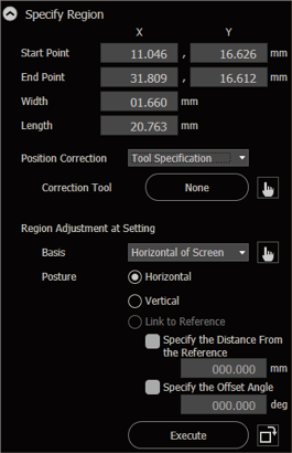
17. Specify Region
Display information for the edge detection area set on the main screen.
The displayed items vary depending on the tool.
A value can also be entered to change the edge detection area.
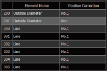
Position Correction
Select the position correction group number to set as the position correction.
To exclude position correction as a target, select [None].
Selecting [Specify Tool] enables set tools (lines, points, circles, chamfer, and corner arc) to be selected.
Position Correction Target
If this check box is cleared, position adjustment is not performed on the set element.
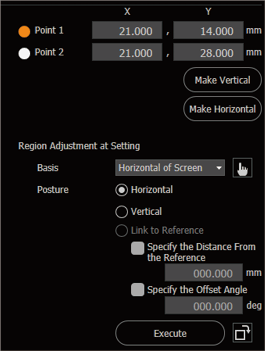
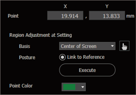
Region Adjustment at Setting
This function adjusts the orientation of the area when creating settings for reference images.
The area for the specified [Basis] can be made horizontal or vertical and aligned with the center or radius.
If a line or circle is set, clicking specifies the reference on the main screen.
Each click of rotates the area 90 degrees.
The offset angle and distance from the reference can be specified.
18. Mask Region
Up to four areas to exclude (mask regions) in the detection area can be specified.
This is useful when the target has a complicated shape or when an area needs to be excluded from the measurement.
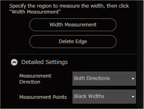
19. Width Measurement
Automatically measure the width of the target.
[Measurement Direction] and [Measurement Points] of edges to be extracted can be selected for [Detailed Settings].
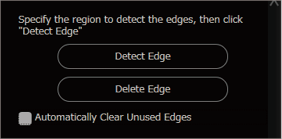
20. Detect Edge
Automatically extract the target edge.
Selecting an extracted edge automatically displays the measurement results.
Selecting [Automatically Clear Unused Edges] and clicking [OK] deletes edges not used in measurement.
21. Delete Edge
Delete edges extracted with [Width Measurement] or [Detect Edge].
22. Output Pattern
Peak Line
Select [Maximum] or [Minimum].
Maximum
Detect the largest edges in the scan direction (the direction of the pink arrow) as peaks and create peak lines with the least square method that go through them.
Minimum
Detect the smallest edges in the scan direction (the direction of the pink arrow) as peaks and create peak lines with the least square method that go through them.
Circle/Connect Arc
Select [Max.], [Min.], [Fitting], [Inscribed], or [Circumscribed].
Maximum
Set “Center of circle found with fitting” as the center based on the detected edge and detect the circle that passes through the furthest edge point from that center.
Minimum
Set “Center of circle found with fitting” as the center based on the detected edge and detect the circle that passes through the closest edge point from that center.
Fitting
Detect a proximate circle using the least square method from the detected edge.
Inscribed
Detects an inscribed circle from the detected edge.
Circumscribed
Detects a circumscribed circle from the detected edge.
Peak Circle/Peak Arc
Select [Maximum] or [Minimum].
Maximum
Detect the largest edge from the center of the circle to the outside as peaks and create peak lines with the least square method that go through them.
Minimum
Detect the smallest edge from the center of the circle to the outside as peaks and create peak lines with the least square method that go through them.
Max/Min Point (Rectangle)
Select [Max point] or [Min point].
Max point
Detect the largest edge point (the furtherest edge point) in the scan direction (the direction of the pink arrow).
Min point
Detect the smallest edge point (the closest edge point) in the scan direction (the direction of the pink arrow).
Max/Min Point (Circle/Arc)
Select [Max point] or [Min point].
Max point
Detects the largest edge point (farthest from the center) from the center of the circle to the outside.
Min point
Detects the smallest edge point (closest to the center) from the center of the circle to the outside.
Approximate Circle
Select [Max.], [Min.], [Fitting], [Inscribed], or [Circumscribed].
Maximum
Set “Center of circle found with fitting” as the center based on the selected point and detect the circle that passes through the furthest point from that center.
Minimum
Set “Center of circle found with fitting” as the center based on the selected point and detect the circle that passes through the closest point from that center.
Fitting
Detect the approximate circle using the least square method from the selected point.
Inscribed
Detects an inscribed circle from the selected point.
Circumscribed
Detects a circumscribed circle from the selected point.
Figure Circle
When specifying a circle and any point to create a figure circle, select [Distance from Center] or [Distance from Circumference].
Distance from Center
Specify the radius of a figure circle with [Radius].
Distance from Circumference
Specify the radius of a figure circle with the radius of the circle specified in STEP 1 and [Radius] as the sum of the specified length.
23. Scan Direction
Select a direction to detect edges. The direction is indicated by the orientation of the pink arrow on the main screen.
Line, Peak Line, Max/Min Point (Rectangle), Inflection, Defect Element
Select either [Forward] (the direction of the pink arrow) or [Reverse] (opposite direction of the pink arrow).
Center Line, Circle, Arc, Peak Circle, Peak Arc, Max/Min Point (Circle/Arc)
Select [Out → Center] or [Center → Out].
24. Correction Method
Set the fitting line correction method.
Maximum
Calculate a proximate line using the least square method from the detected edge. The lines are tilted and the line that goes through the edge of the furtherest (largest) line in the scan direction (the direction of the pink arrow) is detected.
Minimum
Calculate a proximate line using the least square method from the detected edge. The lines are tilted and the line that goes through the edge of the closest (smallest) line in the scan direction (the direction of the pink arrow) is detected.
Fitting
Detect a line using the least square method from the detected edge.
25. Shape
Select whether to detect the convex on the top or the bottom of the reference curve as an inflection when detecting inflection.
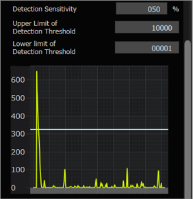
26. Detection sensitivity, Lower Limit of Detection Threshold, Upper Limit of Detection Threshold
Set the inflection detection sensitivity, and upper and lower threshold limits.
The detection status for inflection is displayed on a graph.
27. Display Color Settings
Set the display color of Element and Auxiliary Tool.
28. Reference Line
Select the model line when detecting defect elements.
When [Free Curve Line] is selected for the reference line, specify [Smoothing Range].
The smoothing range increases the value to draw the free curve smoothly on the contour of the measurement target. To make it sharper, decrease the value.
29. Pitch Pattern Settings
When detecting the pitch element, select the pitch pattern from [All Edge Pitches], [Dark-to-Light Edges], [Light-to-Dark Edges], [Black Width], [White Width], [Black Center Widths], and [White Center Widths].
30. Pitch Interval Value
Set the desired value of the pitch element.
31. Half Angle
Select this setting when measuring half angles.
32. Maximum Permissible Feature Count
The number of pitches detected with pitch elements can be restricted to no more than the designated values.
33. Set ALARM as the result when straight line detection fails
The result is set as an alarm when straight line detection fails with pitch element (line angle).
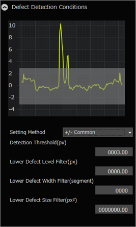
34. Defect Detection Conditions
Set the conditions to detect defects.
The detection status based on the conditions is displayed on a graph.
Setting Method
Select [+/- Common] or [+/- Individual].
Selecting [+/- Individual] enables items to be input individually using [+ Range] and [- Range].
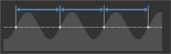
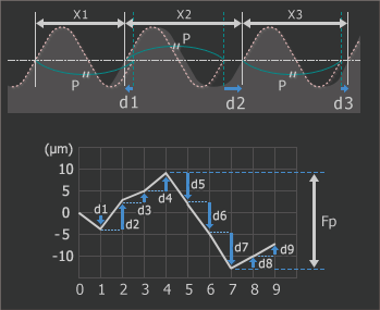
Measure the pitch of the select place on the scan line with the specified measurement pattern.
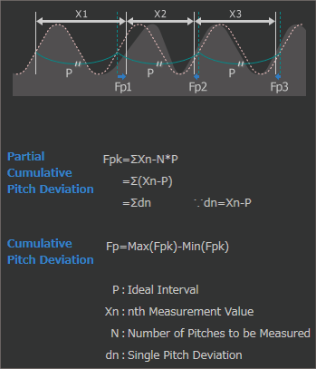
Cumulative Pitch Deviation
Measure the value of the total amplitude (Fp) for the cumulative pitch deviation on the curve.
(This value is the maximum minus the minimum of the partial trail pitch errors on all crests.)
Partial Cumulative Pitch Deviation
Measure the amount of misalignment from the ideal pitch distance with codes. In order to measure correctly, the pitch design value must be entered.
Partial cumulative pitch deviation for Pitch 3 is shown as “Fp3” in the below figure.
Defect Distance
For the direction to detect an object as a defect, select [Absolute Maximum], [Plus], or [Minus].
45. Items to be Judged for Tolerance
Select the items for tolerance judgment based on the pitch distance selected in [Measurement Type].
Average
Set the average pitch distance/angle for tolerance judgment.
Maximum
Set the maximum pitch distance/angle for tolerance judgment.
Minimum
Set the minimum pitch distance/angle for tolerance judgment.
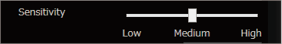
46. Sensitivity
Set the sensitivity (Low/Medium/High) to detect edges in the area.
47. Dead Band
This is the area to be ignored if it is misaligned with the master.
The tolerance range can be set for position misalignment adjustment and the amount of misalignment due to individual differences in the target.
48. Distance from Reference
Specify the distance from the specified reference line to the area to be measured in the [Width of Specific Position] tool.
49. Measurement Method
Select the measurement method for [Distance from Reference] in the [Width of Specific Position] tool.
[Line] can measure the distance between two points by setting a point tool on a position away from the reference.
[Rectangle] can measure the distance between two lines by setting a rectangle edge detection area on the [Distance from Reference] position.
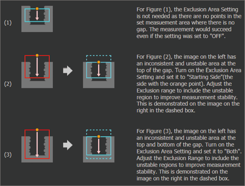
50. Exclusion Area Settings
Set the area to be excluded from measurement with the [Gap] tool.
By setting appropriate values for the area and offset, the gap at the ends of the target can also be measured.
Area
Set the area to be excluded (OFF/Starting Side/Ending Side/Both Sides).
Exclusion Range
Specify how many segments are to be excluded from the specified side of the segments found by the edges (gaps) when searching for edges (gaps) by segment from the starting side or ending side. The range of edges specified to be excluded is shown by a light purple circle (¡).
51. Abnormal Segment Tolerance
Set the allowable number of contiguous segments when areas contain abnormal segments for the [Gap] tool. The alarm will not be triggered if there are contiguous abnormal segments below this number.
Segments will be processed as abnormal segments in the following cases:
Dark (light) widths are detected with the settings that measure light (dark) widths.
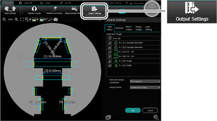
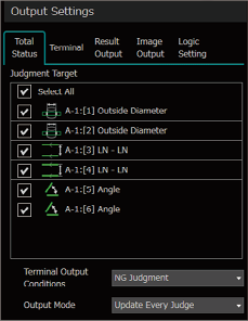
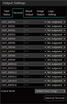
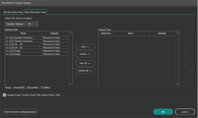
Set the items to output results with EtherNet/IP, PROFINET, PLC-Link, or EtherCAT (CB-NEC20E: Optional).
EtherNet/IP and PROFINET can be used by attaching the communication expansion unit (optional) as well as connecting the field network via the controller’s Ethernet port.
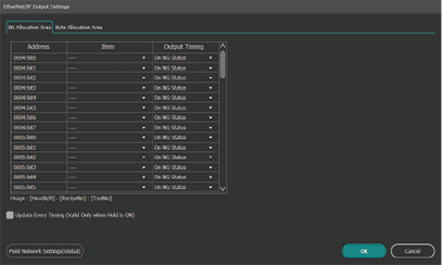
Bit Allocation Area (EtherNet/IP, PROFINET, and EtherCAT)
Byte Allocation Area (EtherNet/IP, PROFINET, PLC-Link, and EtherCAT)
When using this setting with [Hold Mode] set to [ON]
EtherNet/IP, PROFINET, EtherCAT:
Selecting [Update Every Timing] updates the measurement value by inputting TIMING, ZERO, MSR_RESET, and RESET_ALL (the internal measurement value will not update).
PLC-Link:
Selecting [Acknowledge result output completion] and [Enable Handshake] for [Output Results] obtains the updated measurement values.
Settings can only be configured when the communications method is selected in [Global] > [Communications & I/O] > [Field Network].
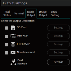
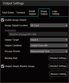
If the check box is selected, image output can be set.
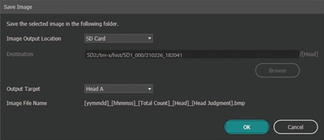
Image Output Location
Select [SD Card], [FTP], or [USB HDD].
[Destination] can be specified only when [FTP] is selected.
To output [Image Output] and [Results Output] to [USB HDD] or [FTP], set the same destination.
Output Target
Set [Head A], [Head B], or [Both].
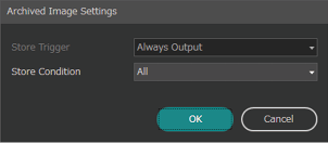
Output Timing
This setting can only be specified when [Hold Mode] is set to [ON].
Select [Every Measurement Period] or [Always Output].
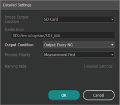
Output Conditions
Select [Output Every NG] or [Always Output].
Process Priority
Select [Measurement First] or [Image First].
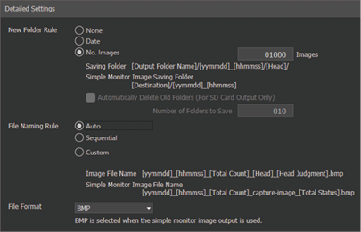
Naming Rule
Set [New Folder Rule], [File Naming Rule], or [File Format].
When [Customize] is selected in [File Naming Rule], the format of the output file name is editable using [Measured Value], [Judgment Result], [Variables], [Date/Time], [String], [Externally Specified String], [Image Specified Info].
However, be careful about the following.
When the file name is blank, the image is not output.
Files with the same name will be overwritten.
For [Head Judgment], when outputting images from a simple monitor, the string will be “capture”.
When [Image Buffer] is on, [Externally Specified String] cannot be reflected correctly (the string will be the one set for measurement).
Output simple monitor image
Configure output settings for images to be displayed on the simple monitor.
[Image Output] is the same for the [Image Output Location], [Priority], and [Naming Rule] settings.
If [Enable Image Output] is selected, these items for simple monitor image output cannot be set.
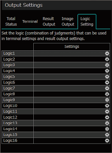
Measurement tool operators (AND/OR) can be set to Logic 1 to 16.
The values displayed here are logical conjunction (AND) or logical disjunction (OR) according to the judgment value (OK=0, NG=1) of the selected tools.
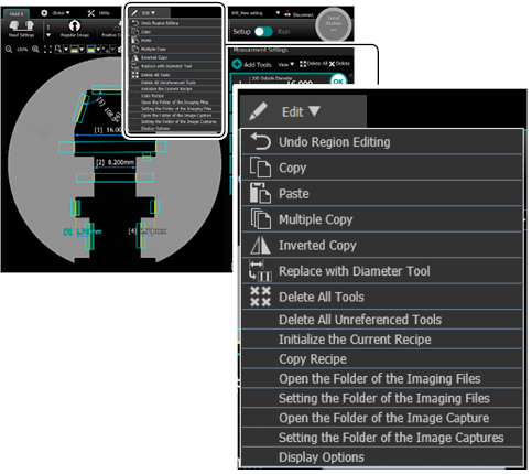
Edit Menu
Undo Region Editing
Movement of the detection region, size changes, and movement of the position where the measurement results are displayed can be restored to the previous position.
Copy
The detection region and measurement tools can be copied.
Paste
Pastes the copied detection region or measurement tool.
The pasted detection region can be moved to the desired position.
Delete all unreferenced element tools and auxiliary tools.
Initialize the Current Recipe
Initializes the displayed recipe.
The values set for [Register Image], [Position Correction], [Measurement Settings], and [Output Settings] are all reset.
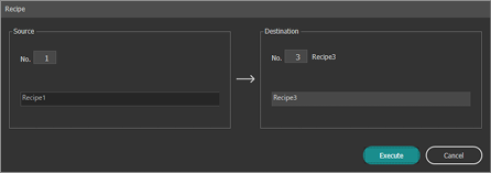
Copy Recipe
This function copies the settings of an existing recipe and pastes them into another recipe.
Specify the source and destination for the recipe number, and then copy the recipe.
The values set for [Register Image], [Position Correction], and [Measurement Settings], are copied.
If two heads are connected, the recipes for both heads are copied.
Open the Folder of the Imaging Files
Open the destination folder where imaging files are saved.
This menu is a TM-X Navigator-only function.
Setting the Folder of the Imaging Files
Set the destination folder to save the imaging files.
Open the Folder of the Image Capture
Opens folders where image captures are saved.
This menu is a TM-X Navigator-only function.
Setting the Folder of the Image Captures
Set the destination folder to save the screen captures.
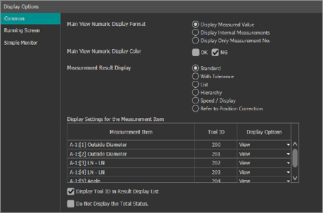
Display Options
Common
Set the items to be displayed on the [Setup] mode and [Run] mode screens.
The following items can be set:
Main View Numeric Display Format
Main View Numeric Display Color
Measurement Result Display
Display Settings for Measurement Items (Select [View], [Show Only List], or [Hide])
Show or hide the Tool ID in Result Display
Do not Display the Total Status
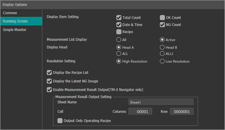
Running Screen
Set the items to be displayed on the screen when changing to [Run] mode.
The following items can be set:
Display Item Setting
Measurement List Display
Display Head
Resolution Setting
Show or Hide the Recipe List.
Show or Hide the Latest NG Images.
Enable or Disable the Measurement Result Output
Measurement Result Output Setting
“Measurement Result Output” is a TM-X Navigator-only function. It is not available with the dedicated display.
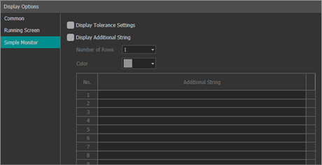
Simple Monitor
Sets the content to be displayed on the simple monitor.
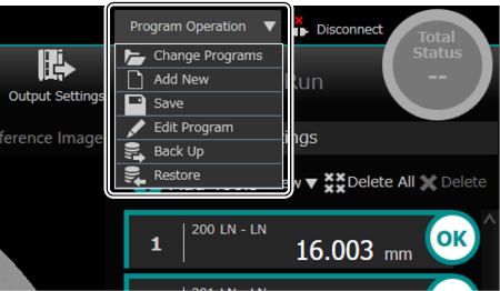
Program Operation
This section describes how to add, save, and edit programs, and other program operations.
Program 000 to 999 can be specified for SD Card 1 and SD Card 2. However, the actual number of programs that can be registered varies depending on the SD memory card capacity and settings.
The system settings file can longer be referenced if SD Card 1 is removed, preventing the controller from operating properly.
The memory used for the SD memory card (in which setting values and other data are saved) is manufactured using highly advanced semiconductor technology. However, repeated data read/write or external noise may cause failure or loss of data. It is strongly recommended that data such as setting values are backed up regularly to other storage media.
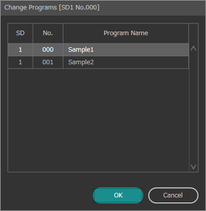
Change Programs
Changes set programs.
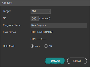
Add New
Add Programs necessary for measurement processing.
[Program Name] can be set at the same time, so register an easy to recognize Program name.
[Program Name] and [Hold Mode] can be edited with [Editing Programs] after a new Program has been added.
Save
Save the active program and global settings.
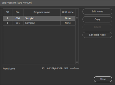
Edit Program
Edit programs saved in the SD memory card.
Edit Name
Program names can be edited.
Copy
Copy the selected Program to another program.
Programs saved on SD Card 1 can also be copied to SD Card 2.
Delete
Delete the selected program.
Edit Hold Mode
The [Hold mode] for the selected program can be changed.
If [Trigger Multiple Times] is enabled in [Head Settings], the [Hold mode] is fixed at [ON].
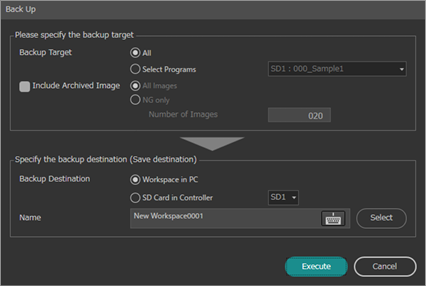
Backup
Back up programs.
Select the program to be backed up and save it to the specified backup destination.
If the dedicated display is being used, [Backup Destination] can be set to [Dedicated Display USB Memory] or [SD Card in Controller].
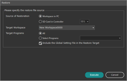
Restore
Restore the program.
To individually restore a program, specify a restore destination first.
If the dedicated display is being used, [Source of Restoration] can be set to [Dedicated Display USB Memory] or [SD Card in Controller].
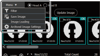
Archived Image
Check archived images for the measurement results.


 ,
,  , or
, or  enables the area to be adjusted.
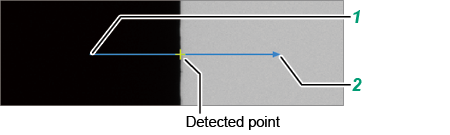
 enables the area to be adjusted.
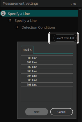
 displays the specified element name.
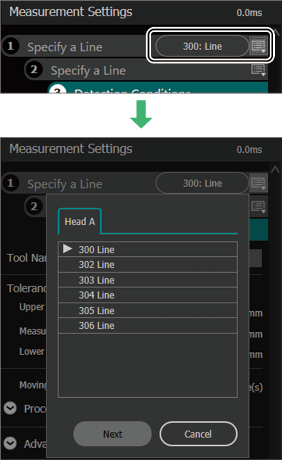
 “Chapter 4 Global Settings/Utility”

 or
or 
 or
or 
 or
or 


 on the right of the list displays a confirmation screen.
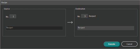


 specifies the reference line on the main screen.
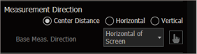

 rotates the area 90 degrees.
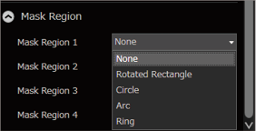
 symbol.