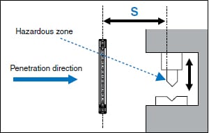
Light Curtain Installation and Safety Distance (Minimum Distance)
When installing a safety light curtain or other electrical detection protective device, refer to the minimum required distances for stopping the machine prior to the body reaching the hazardous zone when the body enters the detection zone. These distances are defined in standards such as ISO 13855. When installing a light curtain, be sure to provide the safety distance (minimum distance) determined by sources such as the standards, regulations, and laws of the country or area in which the light curtain will be used.
Calculating the Safety Distance according to ISO 13855
Safety distance (S) = Approach speed of the body × response time + additional distance (which varies depending on the detection capability of the sensor)
Perpendicular direction of approach
Relationship between the Maximum Time Required by the Machine to Stop and the Safety Distance
The value T shown in the formula is formed by adding the following two parameters. T = Maximum time required by the machine to stop + response time of the light curtain (ON → OFF)
When K (penetration speed) = 2000 mm/s
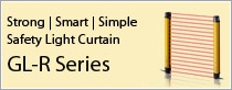
For example, when using the GL-R08H light curtain (which has a response time of 0.0069 s)
S = 2000 mm/s × (maximum time required by the machine to stop + 0.0069 s) + C
As shown above, the maximum time required by the machine to stop is multiplied by the penetration speed (2000 mm/s), so if the maximum time required by the machine to stop is increased by just 1 second, the safety distance is increased by (2000 mm/s × 1 s = 2000 mm). If the light curtain’s response time is increased by 1 ms, the safety distance is increased by 2 mm.
Basic Calculation Examples
Perpendicular direction of approach: GL-R Series
- Calculation Example (1)-1
When using the GL-R60H
(detection capability d = 25 mm and 60 beam axes)
- Condition: Industrial application
K = 2000 mm/s
t1 (GL-R60H response time) = 0.0157s
t2 (maximum time required by the machine to stop) = 0.1s
C = 8 × (25 - 14) = 88 mm
S = K × T + C = 2000 ×(0.1157)+ 88 = 319.4mm
If S is greater than 500 mm, perform the calculation again with K equal to 1600 mm/s. If the newly calculated result gives S less than or equal to 500, set S to 500.
- Calculation Example (1)-2
When using the GL-R08L
(detection capability d = 45 mm and 8 beam axes)
- Condition: Industrial application
K = 1600 mm/s
t1 (GL-R08L response time) = 0.0069 s
t2 (maximum time required by the machine to stop) = 0.1 s
C = 850 mm
S = K × T + C = 1600 × (0.1069) + 850 = 1021.04 mm
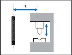
Parallel direction of approach: GL-R Series
- Calculation Example (2)-1
When using the GL-R30L
(detection capability d = 45 mm and 30 beam axes)
- Condition: Industrial application
K = 1600 mm/s
t1 (GL-R30L response time) = 0.0105 s
t2 (maximum time required by the machine to stop) = 0.1 s
H = 200 mm
C = 1200 - 0.4 × 200 = 1120 mm
S = K × T + C = 1600 × (0.0105 + 0.1) + 1120 mm = 1296.8 mm
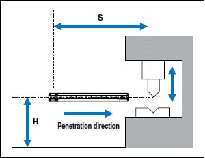
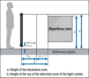
Approaching the hazard by circumventing the top of the detection zone: GL-R Series
When it is not possible to prevent people from passing over the top of the detection zone in order to approach the hazardous zone, it is necessary to determine the height of the light curtain and the minimum distance S while keeping this issue in mind. You have to compare the S value calculated as shown below and the S value calculated under “Perpendicular Direction of Approach: GL-R Series” and set the larger value as the minimum distance S.
CRO is determined as shown in the following table according to the values a (height of the hazardous zone) and b (height of the top of the detection zone of the light curtain).
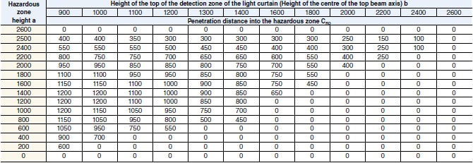
*1 Situations in which the height of the top of the detection zone is less than 900 mm are not included because they cannot provide sufficient protection against circumvention and straddling.
*2 If the bottom of the detection zone is at a height of more than 300 mm from the reference plane, sufficient protection cannot be provided against passing under the detection area to approach the hazard.
- Calculation Example (3)-1
When using the GL-R60H
(detection capability d = 25 mm, 60 beam axes, and detection height of 1180 mm)
- Condition: Industrial application
a (height of the hazardous zone) = 1400 mm
b (height of the top of the detection zone of the light curtain) = 1180 + 300 = 1480 mm
- According to the above table, CRO is 850 mm.
(Because b is 1480 mm, it is between 1400 and 1600. In this situation, use a b value of 1400.)
- K = 1600 mm/s
- t1 (GL-R60H response time) = 0.0157 s
- t2 (maximum time required by the machine to stop) = 0.1 s
- S = K × T + CRO = 1600 × (0.1157) + 850 = 1035.12 mm
(This is larger than the S value calculated under “Perpendicular Direction of Approach: GL-R Series.”)
- Calculation Example (3)-2
When using the GL-R80H
(detection capability d = 25 mm, 80 beam axes, and detection height of 1580 mm)
- Condition: Industrial application
a (height of the hazardous zone) = 1400 mm
b (height of the top of the detection zone of the light curtain) = 1580 + 300 = 1880 mm
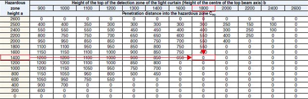
- According to the above table, CRO is 0 mm.
(Because b is 1880 mm, it is between 1800 and 2000. In this situation, use a b value of 1800.)
- K = 2000 mm/s
- t1 (GL-R80H response time) = 0.0192 s
- t2 (maximum time required by the machine to stop) = 0.1 s
- S = K × T + CRO = 2000 × (0.1192) + 0 = 238.4 mm
(This is smaller than the S value calculated under “Perpendicular Direction of Approach: GL-R Series.”)