
Profile Measurement Systems
Overview
Profile measurement systems measure and record the profile of a target by tracing the surface of the target using a stylus. Some instruments can even be used as surface roughness meters. Models with computer numerical control (CNC) are capable of measuring the angles, radii of arcs, height differences, and screw thread pitches. These instruments are ideal for measuring minute shapes such as screw threads and thin films in the order of micrometres.
In recent years, profilometer models have been developed that use a laser instead of a stylus to measure complex shapes by tracing the profile in a non-contact manner. Some models are even able to perform measurements of both the top and bottom surfaces.
These instruments are mostly used in the creation of prototypes to check whether the specifications match the design drawings. They are also applied in reverse engineering.
Construction and Applications
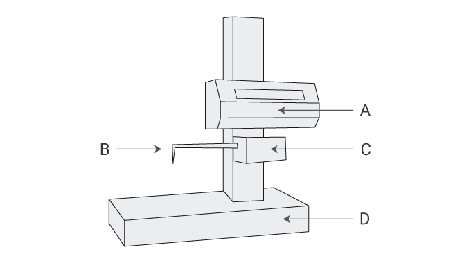
- A
- Drive unit
- B
- Stylus
- C
- Detector
- D
- Measurement table
How to Use a Profile Measurement System
- Attach the stylus to the main unit.
- Perform measurements according to the handling procedure (such as positioning and origin setting).
- Use a jig such as a Y-axis table or a rotating table to automate the measurement.
- The measured data can then be converted and used as various types of CAD data.
Handling Precautions
- Select a stylus suitable for the shape of the target and the purpose of the measurement.
- Especially for models that use a laser, measurements must be performed in an environment free of dust.
- In order to perform correct measurements with high accuracy, use a jig or other tool to correctly position the target on the measuring instrument.
- Calibration is required before using the instrument. Use a dedicated kit to perform the calibration.
