AC Servo Systems
SV series
Single-phase 100 to 115 VAC (for 100 W) SV-010L1
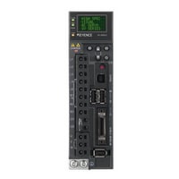
*Please note that accessories depicted in the image are for illustrative purposes only and may not be included with the product.
Specifications
Model | SV-010L1 | |||
Power supply/current capacity and power loss | Maximum applicable motor capacity Single-phase 100 VAC | 100 W | ||
Power capacity (VA) per amplifier Single-phase 100 VAC | 300 VA | |||
Output current Continuous | Single-phase 100 VAC | 0.91 Arms | ||
Output current Maximum | 2.9 Arms | |||
Main circuit power loss Single-phase 100 VAC | 7.8 W | |||
Control circuit power loss Single-phase 100 VAC | 17 W | |||
Total power loss Single-phase 100 VAC | 24.8 W | |||
Input rated current | Main circuit Single-phase 100 VAC | 2.5 Arms | ||
Control circuit Single-phase 100 VAC | 0.38 Arms | |||
Rush current | Main circuit Single-phase 100 VAC | 16.5 A*1 | ||
Control circuit Single-phase 100 VAC | 35 A*1 | |||
General specifications | Type | For 100 V | ||
Capacity | 100W | |||
Input power supply | Voltage/frequency | Main circuit | Single phase 100 to 115 VAC, 50/60 Hz | |
Control circuit | ||||
Main circuit/control circuit | Allowable voltage fluctuation | 85 to 127 VAC | ||
Allowable frequency fluctuation | ±5% or less | |||
Allowable instantaneous outage time | Main circuit | Full (100% down): 0.5 cycle, Partial (50% down): 1 cycle | ||
Control circuit | Approx 65ms | |||
Overvoltage category | III | |||
Control method | 3-phase full-wave rectification, IGBT PWM control, sinusoidal current drive system | |||
Feedback | ||||
Operating environment | Operating ambient temperature | 0 to +55°C (no freezing) | ||
Ambient storage temperature | -20 to +70°C (no freezing) | |||
Ambient operating/storage humidity | 90%RH or less (no condensation) | |||
Vibration resistance | 4.9 m/s2 (conforms to JIS C 60068-2-6) | |||
Shock resistance | 19.6 m/s2 (conforms to JIS C 60068-2-27) | |||
Operating atmosphere (enclosure rating/pollution degree) | Pollution degree: 2 (within a control panel that has a rating of IP54 or higher), however, · No corrosive or flammable gas present · A location that is not subject to water, oil, or drugs · No dust present | |||
Altitude | 1,000 m or less above sea level | |||
Approved standards | UL/CSA standards | UL508C, and CSA C22.2 No.14 | ||
CE marking | Low-voltage directive | EN50178 | ||
EMI | EN55011 Class A, EN61800-3 | |||
EMS | EN61800-3, EN61000-6-2 | |||
North American EMI standards | FCC Part15 B, ICES-003. Class A | |||
Structure | Type | Base mounting attachment | ||
Protection | Open, forced | |||
Lowest insulation resistance value | 1 MΩ or more, tested with a 500 VDC megger | |||
Insulation withstand voltage | 1,500 VAC or more (between the primary side and the earth terminal), 1,800 VAC or more (between the primary side and the secondary side) | |||
Weight | Approx 1.1kg | |||
Performance specifications | Performance | Speed control range | 1 to 5,000 (under the condition that the load torque is less than or equal to the rated torque) | |
Speed fluctuation rate | During load fluctuation | ±0.01% or less with a load fluctuation between 0 and 100% (at the rated rotation speed) | ||
When the voltage of the main circuit fluctuates | 0% at the rated voltage ±10% (at the rated rotation speed) | |||
When the ambient temperature fluctuates | ±0.1% or less when the ambient temperature is between 0 and +50°C (at the rated rotation speed) | |||
Torque control accuracy (reproducibility) | ±1% | |||
Speed frequency response | 1.6 kHz (when JL = JM) * JL: load moment of inertia (motor axis conversion), JM: motor moment of inertia | |||
Dynamic brake | Built-in | |||
Analogue monitor output for observation | Monitor output such as motor rotation speed and torque instruction for observations, number of built-in channels: 2 | |||
Regenerative resistor | Built-in regenerative resistor | None | ||
External regenerative resistor | OP-84399 (220 W*2) | |||
Display function | Access window | Status monitor, parameter settings, calibration, etc. | ||
CHARGE display LED | CHARGE LED (orange) for checking the main circuit power supply input | |||
Status | Servo on, instruction input in progress, warning, MECHATROLINK-II communication in progress | |||
Communication function | USB communication | Function | Status display, parameter settings, calibration, etc. | |
Connection device | PC | |||
Protection function | Overcurrent, overvoltage, insufficient voltage, overload, regeneration error, etc. | |||
Other functions | Auto calibration, absolute position system, etc. | |||
I/O specifications | MECHATROLINK-II type | Control I/O | Input signal: Number of channels | 8CH |
Input signal: Function | Forced stop (FSTOP), forward rotation side limit switch (LSP), reverse rotation side limit switch (LSN), external latch signals 1 to 3 (EXT1, EXT2, EXT3), forward rotation side torque limit selection (PTL), reverse rotation side torque limit selection (NT | |||
Output signal: Number of channels | 4CH | |||
Output signal: Function | Alarm (ALARM), operation preparation complete (RDY), in position (INPOS), speed matching (VCMP), electromagnetic brake timing (BRAKE), torque control in progress (TLM), speed control in progress (VLM), warning (WARN), zero-speed detection (ZSP), near posi | |||
Encoder division pulse output | A-phase (A+, A-), B-phase (B+, B-), Z-phase (Z+, Z-): line-driver output;*3 Z-phase (ZOC): open-collector output; number of division pulses: 1.6 Mpps maximum (6.4 MHz when 2-phase 4× selected)*4 | |||
Communication specifications (MECHATROLINK-II type only) | MECHATROLINK communication | Station address | 41 H to 5 FH (up to 30 slave stations connected) | |
Transmission speed | MECHATROLINK-II | 10 Mbps (selected with access window) | ||
MECHATROLINK-I | 4 Mbps (selected with access window) | |||
Transmission frequency | MECHATROLINK-II | 250 µs, 0.5 to 4.0 ms (multiples of 0.5) | ||
MECHATROLINK-I | 2ms | |||
Transmission byte number | MECHATROLINK-II | 17 bytes/station, 32 bytes/station (selected with access window) | ||
MECHATROLINK-I | 17 bytes/station | |||
Command method | Operation specifications | Position control, speed control, and torque control performed by way of MECHATROLINK communication | ||
Command input | MECHATROLINK-II Command (sequence control Programme/motion/data setting/reference/monitoring/adjustment etc) | |||
I/O terminal specifications and wiring | General-purpose input (DI-1) | Maximum input voltage | 26.4 VDC | |
Input rated voltage | 24 VDC (5mA) | |||
Minimum ON voltage | 19 VDC | |||
Maximum OFF current | 0.1mA | |||
Common ground | Common (MECHATROLINK-II type servo amplifiers only have positive commons.) | |||
General-purpose output (DO-1) | Output | Open-collector output | ||
Rated load | 30 VDC (30mA) | |||
Leakage current (at OFF) | 0.1mA | |||
Residual voltage (at ON) | 1.6 VDC or less | |||
Common ground | Common | |||
2-wire method compatible input (DI-2) | Maximum input voltage | 26.4 VDC | ||
Input rated voltage | 24 VDC (9mA) | |||
Minimum ON voltage | 19 VDC | |||
Maximum OFF current | 1.5mA | |||
Common ground | Common (MECHATROLINK-II type servo amplifiers only have positive commons.) | |||
2-wire method compatible high-speed input (DI-3) | Maximum input voltage | 26.4 VDC | ||
Input rated voltage | 24 VDC (11mA) | |||
Minimum ON voltage | 19 VDC | |||
Maximum OFF current | 1.5mA | |||
Common ground | Common | |||
Z phase open-collector output (DO-2) | Output | Non-isolated open-collector output | ||
Rated load | 30 VDC (30mA) | |||
Leakage current (at OFF) | 0.1mA | |||
Residual voltage (at ON) | 1.2 VDC or less | |||
Common ground | Non-isolated | |||
Output frequency | 50kHz | |||
Encoder output (DO-E) | Output | Differential line-driver output | ||
Output voltage | Corresponds to AM26C31 | |||
Common ground | Independent (non-isolated) | |||
Output frequency | Phase difference: 1.6 Mpps (after 4×: 6.4 MHz) | |||
*1 When used with the amount of current listed above, the duration of the rush current is 20 ms or lower. | ||||