Programmable Controller
KV-5000/3000 series
Specs Programmable Controller KV-5000/3000 series
CPU unit
|
Model |
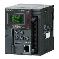
KV-5500 *1 |
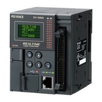
KV-5000 *1 |
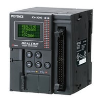
KV-3000 |
|||
|
Image |
|
|
|
|||
|
Type |
CPU Unit |
|||||
|
General specifications |
Power voltage |
24 VDC (±10%) |
||||
|
Operating ambient temperature |
0 to +50°C (with no frost)*2*3 |
0 to +50°C (no freezing)*4*8 |
||||
|
Operating ambient humidity |
10 to 95%RH (no condensation)*4 |
|||||
|
Ambient temperature for storage |
-20 to +70°C*4 |
|||||
|
Storage relative humidity |
10 to 95 % RH (No condensation)*2*5 |
|||||
|
Operating environment |
Without dust and corrosive gas |
|||||
|
Altitude |
2,000 m or less |
|||||
|
Noise immunity |
1,500 Vp-p or more, pulse width: 1 µs, 50 ns (by way of a noise simulator) |
|||||
|
Withstand voltage |
1,500 VAC for 1 minute between the power supply terminal and the I/O terminals and between all the external terminals and the case |
|||||
|
Insulation resistance |
50 MΩ or more (tested with a 500 VDC megger, between the power supply terminal and the I/O terminals and between all the external terminals and the case) |
|||||
|
Shock resistance |
Acceleration 150 m/s2, Operation time 11 ms, twice in each of the X, Y and Z directions |
|||||
|
Overvoltage category |
II (when using KV-U7) |
|||||
|
Pollution degree |
2 |
|||||
|
Vibration resistance |
Intermittent vibration |
Frequency 5 to 9 Hz |
Half amplitude: 3.5 mm*6 |
|||
|
Frequency 9 to 150 Hz |
Acceleration: 9.8 m/s2*6 |
|||||
|
Continuous vibration |
Frequency 5 to 11 Hz |
Half amplitude: 1.75 mm*6 |
||||
|
Frequency 9 to 150 Hz |
Acceleration: 4.9 m/s2*6 |
|||||
|
Performance specifications |
Arithmetic control mode |
Stored program mode |
||||
|
I/O control mode |
Refresh mode |
|||||
|
Program language |
Expanded ladder, KV Script, mnemonic |
|||||
|
Number of commands |
Basic instruction: 81 classes, 182 instructions |
|||||
|
Instruction execution speed |
Basic instruction: Min. 10 ns |
|||||
|
Program capacity |
Approx. 260k steps |
Approx. 160k steps |
||||
|
Maximum number of units to be installed |
16 units (48 units when expansion units are connected) |
|||||
|
Maximum number of I/O points |
Maximum 3,096 points for expansion (KV-EB1S/KV-EB1R: When 2 units are expanded, 64-point I/O unit is used) |
|||||
|
Bit device |
Input relay R |
Total 16,000 points 1 bit |
||||
|
Output relay R |
||||||
|
Internal auxiliary relay R |
||||||
|
Link relay B |
16,384 points 1 bit |
|||||
|
Internal auxiliary relay MR |
16,000 points 1 bit |
|||||
|
Latch relay LR |
||||||
|
Control relay CR |
640 points 1 bit |
|||||
|
Word device |
Timer T |
4,000 points 32 bits |
||||
|
Counter C |
||||||
|
Data memory DM |
65,535 points 16 bits |
|||||
|
Expansion data memory EM |
||||||
|
File register |
Memory bank switching mode FM |
32,768 points × 4 memory banks 16 bits |
||||
|
Dial mode ZF |
131,072 points 16 bits |
|||||
|
Link register W |
16,384 points 16 bits |
|||||
|
Temporary data memory TM |
512 points 16 bits |
|||||
|
High-speed counter CTH |
2 points 32 bits |
|||||
|
4 points 32 bits (2 points for one high-speed counter) |
||||||
|
Index register Z |
12 points 32 bits |
|||||
|
Control memory CM |
6,000 points 16 bits |
|||||
|
Positioning pulse output |
2 points (maximum output frequency: 100 kHz) |
|||||
|
CPU unit I/O |
Input: 16 points, output: 8 points |
|||||
|
Power failure hold function |
Program memory |
Flash ROM can be rewritten 100,000 times |
||||
|
Device |
5 years (operating ambient temperature of 25°C in the power failure hold mode)*7 |
|||||
|
Self-diagnosis function |
CPU abnormal, RAM abnormal, other |
|||||
|
Internal current consumption |
CPU unit: 320 mA or less |
|||||
|
Weight |
CPU unit: approx. 320 g |
CPU unit: approx. 300 g |
||||
|
*1 This product is not available for sale in China and cannot be ordered for shipment to China. |
||||||
Input unit
|
Model |
KV-B16XC |
KV-C32XC |
KV-C64XC |
|||
|
Image |
|
|
|
|||
|
Type |
Input unit |
|||||
|
External connection mode |
Removable terminal block |
Connector (MIL specification)*3 |
||||
|
Input |
Number of inputs |
16 points |
32 points |
64 points |
||
|
Input mode |
24 VDC mode, 5 VDC mode |
24 VDC mode*4 |
||||
|
Max. input voltage |
26.4 VDC |
|||||
|
Rated input voltage |
24 VDC mode: 24 VDC 5.3 mA, 5 VDC mode: 5 VDC 1 mA |
24 VDC 4.1 mA |
||||
|
Min. ON voltage |
24 VDC mode: 19 V, 5 VDC mode: 3.5 V |
19 V |
||||
|
Max. OFF current |
24 VDC mode: 1.5 mA |
1.5 mA |
||||
|
Max. OFF voltage |
5 VDC mode: 1.5 V |
- |
||||
|
Common point mode |
16 points/1 common point (2 terminals)*1 |
32 points/1 common point (2 terminals)*1 |
32 points/1 common point (4 terminals)*5 |
|||
|
Input time constant |
[Input time constant setting 25 µs] OFF to ON: TYP 25 µs/MAX 65 µs, ON to OFF: TYP 75 µs/MAX 120 µs |
|||||
|
Input impedance |
4.3 kΩ |
5.6 kΩ |
||||
|
Internal current consumption |
15 mA or less |
25 mA or less |
||||
|
Weight |
Approx. 120 g |
Approx. 110 g |
Approx. 140 g |
|||
|
*1 Even though KV-B16XC and KV-C32XC have two common points, they are the same internally. |
||||||

Output unit
|
Model |
KV-B16RC |
KV-B8RC |
KV-B16TD |
KV-B16TCP |
|||
|
Image |
|
|
|
|
|||
|
Type |
Output unit |
||||||
|
External connection mode |
Removable terminal block |
||||||
|
Output |
Number of outputs |
16 points |
8 points |
16 points |
|||
|
Output form |
Relay |
MOS-FET (sink) (with overcurrentprevention function) |
Transistor (source) |
||||
|
Rated load |
250 VAC/30 VDC 2 A (8 A/1 common point) |
250 VAC/30 VDC 2 A |
30 VDC 0.3 A |
30 VDC 0.2 A |
|||
|
Leak current at OFF |
- |
100 µA or less |
|||||
|
Residual voltage at ON |
0.5 V or less |
||||||
|
ON resistance |
50 mΩ or less |
- |
|||||
|
Common point mode |
8 points/1 common points |
Independent |
16 points/1 common point (2 terminals)*1 |
||||
|
Operating time |
OFF to ON/ON to OFF: 10 ms or less |
OFF to ON: 100 µs or less、ON to OFF: 300 µs or less |
OFF to ON: 10 µs or less、ON to OFF: 200 µs or less |
||||
|
Internal current consumption |
120 mA or less |
65 mA or less |
45 mA or less |
35 mA or less |
|||
|
Weight |
Approx. 190 g |
Approx. 160 g |
Approx. 130 g |
||||
|
*1 Although KV-B16TD, KV-C32TD, KV-B16TCP, and KV-C32TCP have two points, they are the same internally. |
|||||||
Output unit
|
Model |
KV-C32TD |
KV-C32TCP |
KV-C64TD |
KV-C64TCP |
|||
|
Image |
|
|
|
|
|||
|
Type |
Output unit |
||||||
|
External connection mode |
Connector (MIL specification)*1 |
||||||
|
Output |
Number of outputs |
32 points |
64 points |
||||
|
Output form |
MOS-FET (sink) (with overcurrentprevention function) |
Transistor (source) |
MOS-FET (sink) (with overcurrentprevention function) |
Transistor (source) |
|||
|
Rated load |
30 VDC 0.2 A |
||||||
|
Leak current at OFF |
100 µA or less |
||||||
|
Residual voltage at ON |
0.5 V or less |
||||||
|
ON resistance |
- |
||||||
|
Common point mode |
32 points/1 common point (2 terminals)*2 |
64 points/1 common point (4 terminals)*3 |
|||||
|
Operating time |
OFF to ON: 100 µs or less、ON to OFF: 300 µs or less |
OFF to ON: 10 µs or less、ON to OFF: 200 µs or less |
OFF to ON: 150 µs or less、ON to OFF: 300 µs or less |
OFF to ON: 50 µs or less、ON to OFF: 200 µs or less |
|||
|
Internal current consumption |
65 mA or less |
55 mA or less |
120 mA or less |
100 mA or less |
|||
|
Weight |
Approx. 100 g |
Approx. 140 g |
|||||
|
*1 Connectors for connector-type I/O units are not included. MIL34-pin slender connector kit OP-42224 and MIL34-pin connector kit OP-23139 are available separately. |
|||||||
I/O unit
|
Model |
KV-B8XTD |
KV-C16XTD |
KV-C32XTD |
|||
|
Image |
|
|
|
|||
|
Type |
I/O unit |
|||||
|
External connection mode |
Removable terminal block |
Connector (MIL standard)*2 |
||||
|
Input |
Number of inputs |
8 points |
16 points |
32 points |
||
|
Input mode |
24 VDC mode, 5 VDC mode |
24 VDC mode*3 |
||||
|
Max. input voltage |
26.4 VDC |
|||||
|
Rated input voltage |
24 VDC mode: 24 VDC 5.3 mA, 5 VDC mode: 5 VDC 1 mA |
24 VDC 4.1 mA |
||||
|
Min. ON voltage |
24 VDC mode: 19 V, 5 VDC mode: 3.5 V |
19 V |
||||
|
Max. OFF current |
24 VDC mode: 1.5 mA |
1.5 mA |
||||
|
Max. OFF voltage |
5 VDC mode: 1.5 V |
- |
||||
|
Common point mode |
8 points/1 common point (1 terminal) |
16 points/1 common point (1 terminal) |
32 points/1 common point (2 terminals)*4 |
|||
|
Input time constant |
25 µs/300 µs*1/1 ms/10 ms |
|||||
|
Input impedance |
4.3 kΩ |
5.6 kΩ |
||||
|
Output |
Number of outputs |
8 points |
16 points |
32 points |
||
|
Output form |
MOS-FET (N ch) (with an overcurrent-proof function) |
|||||
|
Rated load |
30 VDC 0.3 A |
30 VDC 0.2 A |
||||
|
Leak current at OFF |
100 µA or less |
|||||
|
Residual voltage at ON |
0.5 V or less |
|||||
|
Common point mode |
8 points/1 common point (1 terminal) |
16 points/1 common point (1 terminal) |
32 points/1 common point (2 terminals)*4 |
|||
|
Operating time |
OFF to ON: 100 µs or less, ON to OFF: 300 µs or less |
OFF to ON: 150 µs or less, ON to OFF: 300 µs or less |
||||
|
Internal current consumption |
30 mA or less |
40 mA or less |
65 mA or less |
|||
|
Weight |
Approx. 130 g |
Approx. 110 g |
Approx. 130 g |
|||
|
*1 Setup is only possible when KV-7500/7300/5500/5000/3000 is connected. When KV-1000/700 is connected, selection is not possible. |
||||||
A/D and D/A conversion unit
|
Model |
KV-AM40V |
|||
|
Image |
|
|||
|
Type |
A/D and D/A conversion unit |
|||
|
Analogue I/O point |
Input: 2 points (differential input), Output: 2 points |
|||
|
Analogue I/O range (resolution) |
Voltage |
-10 to +10 V (1.25 mV 1/16,000) |
||
|
Input current |
0 to 20 mA (2.5 µA 1/8,000) |
|||
|
Input resistance |
Voltage: 5 MΩ, Current: 250 Ω |
|||
|
Conversion speed |
80 µs/ch*2*3 |
|||
|
Conversion precision |
±0.2 % of F.S. (25 °C ±5 °C), ±0.4 % of F.S. (0 to 50 °C)*4 |
|||
|
Insulation mode |
Between unit and CPU: Photocoupler insulation, Among channels: Not insulated |
|||
|
Absolute max. input |
Voltage: ±15 V, Current: 30 mA |
|||
|
Min. load resistance |
Voltage: 1 kΩ |
|||
|
Max. load resistance |
Current: 600 Ω |
|||
|
Internal current consumption |
140 mA or less |
|||
|
Weight |
Approx. 150 g |
|||
|
*1 Analogue output is not available within the range of -5 to +5 V. |
||||
Multi-input PID temperature control unit
|
Model |
KV-TF40 |
|||
|
Image |
|
|||
|
Type |
Multi-input PID temperature control unit |
|||
|
Memory elements |
EEPROM rewritable one million times |
|||
|
Number of temperature input points |
4 ch |
|||
|
Input |
Thermocouple/Platinum temperature measuring resistor*1 |
|||
|
Temperature sensor types |
Thermocouple: K, J, T, E, R, B, N, S, W5Re/W26Re |
|||
|
Indicated accuracy |
±0.3 % of F.S. ±1 digit (+25 °C), ±0.7 % of F.S. ±1 digit (0 to +50 °C) |
|||
|
Cold junction correction precision |
±1 °C |
|||
|
Sampling period |
125 ms/ch (500 ms/4 ch) |
|||
|
Control period |
1 to 100 sec. |
|||
|
Operating mode |
PID control (with auto-tuning and 3 mode stabiliser function installed) |
|||
|
Tuning mode |
PID auto-tuning mode |
|||
|
Control output |
transistor (sink) |
|||
|
Alarm output |
transistor (sink)*2 |
|||
|
Alarm mode |
Absolute value upper limit, absolute value lower limit, deviation upper limit, deviation lower limit, |
|||
|
Output |
Rated load |
30 VDC 100 mA or less |
||
|
Leak current at OFF |
100 µA or less |
|||
|
Residual voltage at ON |
1.5 V or less |
|||
|
Current sensor (CT) input |
4 ch*4 |
|||
|
Current measurement precision |
Larger of ±5 % of an input value and ±2 A of an input value |
|||
|
Insulation mode |
Between inputs and outputs: Photocoupler and transformer insulation, |
|||
|
Other functions |
Heater wire breaking alarm, control loop wire breaking alarm, measured value bias, |
|||
|
Internal current consumption |
210 mA or less |
|||
|
Weight |
Approx. 270 g |
|||
|
*1 Can be set for each channel. |
||||
Temperature and analogue multi-input unit
|
Model |
KV-TP40 |
|||
|
Image |
|
|||
|
Type |
Temperature and analogue multi-input unit |
|||
|
Number of temperature input points |
4 ch |
|||
|
Input |
Thermocouple/Platinum temperature measuring resistor/Voltage and current |
|||
|
Input range |
Thermocouple |
K: -270.0 to 1,372.0 °C |
||
|
Platinum temperature measuring resistor |
Pt100: -200.0 to 850.0 °C |
|||
|
Voltage and current |
Voltage: |
|||
|
Indicated accuracy |
±0.2 % of F.S. (25 ±5 °C), ±0.4 % of F.S. (0 to 50 °C) |
|||
|
Cold junction correction precision |
±1 °C (during thermocouple input) |
|||
|
Input resistance |
Voltage: 1 MΩ, Current: 250 Ω |
|||
|
Conversion speed |
50 ms/4 ch |
|||
|
Insulation mode |
Between an input terminal and CPU: Photocoupler transformer insulation, |
|||
|
Other functions |
External cold junction correction, wire-breaking detection function, scaling function, |
|||
|
Internal current consumption |
90 mA or less |
|||
|
Weight |
Approx. 190 g |
|||
Serial communication unit
|
Model |
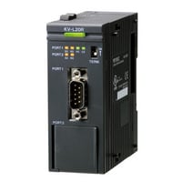
KV-L20R*1 |
|||
|
Image |
|
|||
|
Type |
Serial communication unit |
|||
|
Connection interface |
Port 1: RS-232C, Port 2: RS-232C/RS-422A/RS-485 (4 wires) /RS-485 (2 wires) switching |
|||
|
Transmission specification |
Transmission rate |
1,200, 2,400, 4,800, 9,600, 19,200, 38,400, 57,600, 115,200 bps |
||
|
Transmission method |
RS-232C, RS-422A, RS-485 (4 wires): Full duplex RS-485 (2 wires): Half duplex |
|||
|
Transmission distance |
RS-232C: 15 m or less, RS-422A, RS-485 (4 wires)/RS-485 (2 wires): Total extension 500 m or less |
|||
|
Internal current consumption |
120 mA or less |
|||
|
Weight |
Approx. 160 g |
|||
|
*1 The KV-L20R cannot be connected to the KV-5500/5000/3000. |
||||
DeviceNet unit
|
Model |
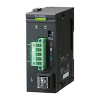
KV-DN20 |
|||
|
Image |
|
|||
|
Type |
DeviceNet® unit |
|||
|
Communication protocol |
Compliant with DeviceNet® |
|||
|
Transmission specification |
Transmission rate |
500 kbps, 250 kbps, 125 kbps |
||
|
Transmission media |
5 dedicated cables (2 for signal system, 2 for power, 1 for shield line) |
|||
|
Connection topology |
Multidrop method |
|||
|
Maximum cable length |
Thick main cable 500 m (Transmission speed 125 kbps), 250 m (Transmission speed 250 kbps), 100 m (Transmission speed 500 kbps) |
|||
|
Maximum number of nodes |
64 (including master, slave, configurator) |
|||
|
Master mode |
Connected pieces per network |
Max. 64 |
||
|
Type of communication |
I/O communication (Poll/Bit-Strobe/COS/Cyclic), Explicit message communication |
|||
|
Type and size of assigned devices |
Relay or data memory (indicated per block) |
|||
|
Assignment method of device |
Auto configuration (Fixed or assigned with front end) and manual assignment |
|||
|
Slave connection pieces per unit |
Max. 63 |
|||
|
Maximum number of I/O per slave |
Input: 2048 points (128 words), Output: 2048 points (128 words) |
|||
|
Data length of message communication |
Sending: 106 bytes, receiving 110 bytes |
|||
|
Slave mode |
Connected pieces per network |
Max. 64 |
||
|
Type of communication |
I/O communication (Poll), Explicit message communication |
|||
|
Type and size of assigned devices |
Relaying or data memory |
|||
|
Internal current consumption |
Internal circuit: 24 VDC 45 mA or less (supplied by CPU unit) |
|||
|
Weight |
Approx. 150 g |
|||
Error output unit
|
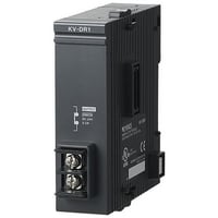
Model |
KV-DR1 |
|||
|
Image |
|
|||
|
Type |
Error output unit |
|||
|
Error output |
Output form |
Relay |
||
|
Rated load |
24 VDC 0.5 A |
|||
|
ON resistance |
50 mΩ or less |
|||
|
Response time |
OFF to ON 10 ms or less, ON to OFF 5 ms or less |
|||
|
Relay life |
Electrical life: 100,000 times or more (20 times/min.) |
|||
|
Relay exchange |
Impossible |
|||
|
Internal current consumption |
5 VDC 30 mA or less (supplied from the CPU unit) |
|||
|
Weight |
Approx. 90 g |
|||