Programmable Logic Controller
KV-8000 series
Contact Us: 1-800-103-0090 Enquiry form
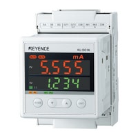
DC Current Input Unit KL-DC1A

*Please note that accessories depicted in the image are for illustrative purposes only and may not be included with the product.
Specifications
Model | KL-DC1A | |||
General specifications | Measurement type | DC current | ||
Power voltage | 24 VDC ± 10%, Class 2 | |||
Operating ambient temperature | 0 to +50°C (no freezing) | |||
Operating ambient humidity | 35 to 85%RH(no condensation) | |||
Ambient temperature for storage | -20 to +70°C | |||
Operating environment | Minimal amount of dust and corrosive gas present | |||
Measurement category | - | |||
Wire temperature rating | +70°C or more | |||
Noise immunity | 1,500 Vp-p or more, pulse width: 1 µs, 50 ns (by way of a noise simulator), conforms to IEC standards (IEC 61000-4-2/-3/-4/-6) | |||
Withstand voltage | 1,500 VAC for 1 minute (between the power supply terminal and each terminal and between all the terminals and the case) | |||
Insulation resistance | 100 MΩ or more (tested with a 500 VDC megger, between the power supply terminal and each I/O terminal and between all the terminals and the case) | |||
Internal current consumption (excluding current for driving input circuits) | 170mA or less | |||
Shock resistance | Conforms to JIS B 3502 and IEC 61131-2, 147 m/s2, operating time: 11 ms, 3 times in each of the 3 directions | |||
Pollution degree | 2 | |||
Vibration resistance | Intermittent vibration | Frequency: 10 to 57 Hz | Amplitude: 0.075 mm*1 | |
Frequency: 57 to 150 Hz | Acceleration: 9.8 m/s2*1 | |||
Continuous vibration | Frequency: 10 to 57 Hz | Amplitude: 0.035 mm*1 | ||
Frequency: 57 to 150 Hz | Acceleration: 4.9 m/s2*1 | |||
Weight | approx 350g | |||
Performance specifications | Number of channels | 1CH | ||
Number of ranges | 5 (Range 1 and range 2 are shared among the terminals.) | |||
Range switching | Setting: Use the setting switch. Connection: The connection terminal varies depending on the range. | |||
Input method | Single-ended | |||
Sampling rate | Normal mode: 1 ms (1,000 times/sec.), high-precision mode: 100 ms (10 times/sec.) | |||
Input range*2 | Range 1: 0 to 20 mA, range 2: ±10 mA, range 3: ±100 mA, range 4: ±1 A, range 5: ±10 A*2 | |||
Displayable range | Range 1: 0 to 20 mA | -1.00 to 21.00mA*3 | ||
Range 2: ±10 mA | -10.999 to 10.999mA*3 | |||
Range 3: ±100 mA | -100.99 to 100.99mA*3 | |||
Range 4: ±1 A | -1099.9 to 1099.9mA*3 | |||
Range 5: ±10 A | -10.999 to 10.999A*3 | |||
Resolution | Normal | Range 1: 0 to 20 mA | 10 µA*4 (0.01 mA; 1/2000)*2 | |
Range 2: ±10 mA | 1 µA (0.001 mA; 1/20000)*2 | |||
Range 3: ±100 mA | 10 µA (0.01 mA; 1/20000)*2 | |||
Range 4: ±1 A | 100 µA (0.1 mA; 1/20000)*2 | |||
Range 5: ±10 A | 1mA | |||
High accuracy | Range 1: 0 to 20 mA | 0.1 µA (1/200000)*2 | ||
Range 2: ±10 mA | ||||
Range 3: ±100 mA | 1 µA (0.001 mA; 1/200000)*2 | |||
Range 4: ±1 A | 10 µA (0.01 mA; 1/200000)*2 | |||
Range 5: ±10 A | 0.1mA | |||
Input impedance | Range 1: 0 to 20 mA | 10 Ω | ||
Range 2: ±10 mA | ||||
Range 3: ±100 mA | 1 Ω | |||
Range 4: ±1 A | 0.1 Ω | |||
Range 5: ±10 A | 10 MΩ | |||
Absolute maximum input current | Range 1: 0 to 20 mA | ±100 mA | ||
Range 2: ±10 mA | ||||
Range 3: ±100 mA | ±500 mA | |||
Range 4: ±1 A | ±3 A | |||
Range 5: ±10 A | ±12 A | |||
Measurement accuracy (25 ±5°C) | Range 1: 0 to 20 mA | ±0.2% of F.S. ± 1 digit | ||
Range 2: ±10 mA | ||||
Range 3: ±100 mA | ||||
Range 4: ±1 A | ±0.3% of F.S. ± 1 digit | |||
Range 5: ±10 A | ±0.5% of F.S. ± 1 digit*5 | |||
Measurement accuracy (0 to 50°C) | Range 1: 0 to 20 mA | ±0.6% of F.S. ± 1 digit | ||
Range 2: ±10 mA | ||||
Range 3: ±100 mA | ||||
Range 4: ±1 A | ±0.7% of F.S. ± 1 digit | |||
Range 5: ±10 A | ±0.9% of F.S. ± 1 digit*5 | |||
Control input | 2 (Parameters are used to switch between the KL input, peak/bottom hold control input, and 0-point adjustment input.) | |||
Controloutput | 2 transistor (NPN open-collector) outputs (Parameters are used to switch between the KL output and comparator output.) | |||
Setting data | Recorded to the EEPROM (rewritable 1,000,000 times) | |||
Other functions | Hold (peak and bottom), 0-point adjustment, comparator output, filter setting (LPF and HPF), time average (simple and moving), scaling setting, display unit changing, lock | |||
Control I/O specifications | External calibration input signal | Number of inputs | 2 | |
Maximum input voltage | DC26.4V | |||
Input rated voltage | DC24V 5.3mA | |||
Minimum ON voltage | 19V | |||
Maximum OFF current | 1.5mA | |||
Common ground | 2/common | |||
Input time constant | 10ms | |||
Control output | Number of outputs | 2 | ||
Output | Transistor NPN output | |||
Rated load | DC30V 0.1A | |||
Peak load current | 0.2A | |||
Leakage current (at OFF) | 100 µA or less | |||
Residual voltage (at ON) | DC0.8V or less | |||
Common ground | 2/common | |||
ON/OFF response time | Off to on: 10 µs or less (between 5 and 100 mA), on to off: 50 µs or less (between 5 and 100 mA) | |||
KL link specifications | Supported master units | Model: KL-N20V, supported PLC: KEYENCE KV-1000/700; model: KL-N10V, supported PLC: KEYENCE KV-10/16/24/40; model: KV-P16*L (built-in PLC), supported PLC: KEYENCE; model: KL-N20A, supported PLC: Mitsubishi AnA, AnA, AnU, QnA, AnSH, and Q2AS; model: KL-N20C, supported PLC: Omron C200H/HS, SYSMAC α, and CS1 (excluding the C200H-02/22), KEYENCE VT2-12F/10F/10T/10S/8T/8S/7S/5T/5S/5M and DT-100 | ||
Communication address | 00 H to FE H(0 to 254) | |||
Number of occupied words | EASY mode: reception (KL to PLC): 5 words, transmission (PLC to KL): 3 words; FULL mode: reception (KL to PLC): 7 words, transmission (PLC to KL): 5 words*6 | |||
Communication speed | 2.5 Mbps, 625 kbps, 156 kbps (set with parameters)*7 | |||
*1 Conforms to JIS B 3502, IEC61131-2 | ||||


