Safety Light Curtain
GL-R series
Specs Safety Light Curtain GL-R series
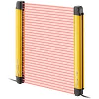
GL-RF Detection capability ø14mm:Total length 240 to 560mm
|
Model |
GL-R23F |
GL-R31F |
GL-R39F |
GL-R47F |
GL-R55F |
|||
|
Image |
|
|
|
|
|
|||
|
Detection capability |
ø14 mm |
|||||||
|
Total length |
240mm |
320mm |
400mm |
480mm |
560mm |
|||
|
No. of beam |
23 |
31 |
39 |
47 |
55 |
|||
|
Detection height |
220mm |
300mm |
380mm |
460mm |
540mm |
|||
|
Protection height |
244mm |
324mm |
404mm |
484mm |
564mm |
|||
|
Beam axis spacing/Lens diameter |
10 mm / ø4 |
|||||||
|
Detecting distance |
0.2 to 10 m*1 |
|||||||
|
Effective aperture angle |
Max. ±2.5° (When operating distance is 3 m or more) |
|||||||
|
Light source |
Infrared LED (870 nm) |
|||||||
|
Response time (OSSD) (ms) |
Wire synchronisation, One-line or |
ON→OFF |
6.9 |
7.8 |
8.6 |
9.5 |
10.4 |
|
|
OFF→ON |
49.2*2 |
50.5*2 |
51.8*2 |
53.1*2 |
54.3*2 |
|||
|
All blocked→ON |
64.4*3 |
67.9*3 |
71.3*3 |
74.8*3 |
78.3*3 |
|||
|
Optical synchronisation system |
ON→OFF |
9.3 |
10.7 |
12.1 |
13.5 |
14.9 |
||
|
OFF→ON |
52.7*2 |
54.8*2 |
56.9*2 |
59*2 |
61.1*2 |
|||
|
All blocked→ON |
74*3 |
79.5*3 |
85.1*3 |
90.7*3 |
96.3*3 |
|||
|
Detection mode |
Turns on when no interruptions are present in the detection zone |
|||||||
|
Synchronisation between the transmitter and receiver |
Optical synchronisation or Wire synchronisation (Determined by wiring) |
|||||||
|
Light interference prevention function |
Prevents mutual interference in up to two GL-R systems. |
|||||||
|
Control output |
Output |
2 transistor outputs. (PNP or NPN is determined by the cable type) |
||||||
|
Max. load current |
500 mA*4 |
|||||||
|
Residual voltage (during ON) |
Max. 2.5 V (with a cable length of 5 m) |
|||||||
|
OFF state voltage |
Max. 2.0 V (with a cable length of 5 m) |
|||||||
|
Leakage current |
Max. 200 µA |
|||||||
|
Max. capacitive load |
2.2 µF |
|||||||
|
Load wiring resistance |
Max. 2.5 Ω |
|||||||
|
Supplemental output |
AUX |
transistor outputs. (PNP or NPN is determined by the cable type) |
||||||
|
Error output |
||||||||
|
Muting lamp output |
Incandescent lamp (24 VDC, 1 to 5.5 W) |
|||||||
|
External input |
When using a PNP output cable |
EDM input |
ON voltage: 10 to 30 V |
|||||
|
When using an NPN output cable |
EDM input |
ON voltage: 0 to 3 V |
||||||
|
Power supply |
Power voltage |
24 VDC ±20%, ripple (P-P) 10% or less, Class 2 |
||||||
|
Current |
Transmitter |
50 |
54 |
57 |
60 |
62 |
||
|
Receiver |
70 |
71 |
72 |
74 |
75 |
|||
|
Protection circuit |
Reverse current protection, short-circuit protection for each output, surge protection for each output |
|||||||
|
Approved standards |
EMC |
EMS |
IEC61496-1, EN61496-1, UL61496-1 |
|||||
|
EMI |
EN55011 ClassA, FCC Part15B ClassA, ICES-003 ClassA |
|||||||
|
Safety |
IEC61496-1, EN61496-1, UL61496-1 (Type 4 ESPE) |
|||||||
|
Environmental resistance |
Enclosure rating |
IP65/IP67 (IEC60529) |
||||||
|
Overvoltage category |
II |
|||||||
|
Ambient light |
Incandescent lamp: 3,000 lux or less, Sunlight: 20,000 lux or less |
|||||||
|
Operating ambient temperature |
-10 to +55 °C (No freezing) |
|||||||
|
Operating relative humidity |
15 to 85 % RH (No condensation) |
|||||||
|
Storage temperature |
-25 to +60 °C (No freezing) |
|||||||
|
Storage relative humidity |
15 to 95 % RH |
|||||||
|
Vibration resistance |
10 to 55 Hz, Double amplitude 0.7 mm, 20 sweeps in each of the X, Y, and Z directions |
|||||||
|
Shock resistance |
100 m/s2 (Approx. 10 G), 16 ms pulse, 1,000 times in each of the X, Y, and Z directions |
|||||||
|
Material |
Main unit case |
Aluminium |
||||||
|
Upper case/lower case |
Nylon (GF 30%) |
|||||||
|
Front cover |
Polycarbonate, SUS304 |
|||||||
|
Weight |
Transmitter |
320 g |
430 g |
550 g |
660 g |
780 g |
||
|
Receiver |
330 g |
440 g |
670 g |
|||||
|
*1 When the option front protection cover is installed on the one of transmitter or receiver, the Operating distance is shorten by 0.5 m. When the front covers are installed on both of the transmitter and receiver, the Operating distance is shorten by 1.0 m. |
||||||||


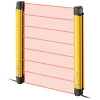
GL-RF Detection capability ø14mm:Total length 640 to 960mm
|
Model |
GL-R63F |
GL-R71F |
GL-R79F |
GL-R87F |
GL-R95F |
|||
|
Image |
|
|
|
|
|
|||
|
Detection capability |
ø14 mm |
|||||||
|
Total length |
640mm |
720mm |
800mm |
880mm |
960mm |
|||
|
No. of beam |
63 |
71 |
79 |
87 |
95 |
|||
|
Detection height |
620mm |
700mm |
780mm |
860mm |
940mm |
|||
|
Protection height |
644mm |
724mm |
804mm |
884mm |
964mm |
|||
|
Beam axis spacing/Lens diameter |
10 mm / ø4 |
|||||||
|
Detecting distance |
0.2 to 10 m*1 |
|||||||
|
Effective aperture angle |
Max. ±2.5° (When operating distance is 3 m or more) |
|||||||
|
Light source |
Infrared LED (870 nm) |
|||||||
|
Response time (OSSD) (ms) |
Wire synchronisation, One-line or |
ON→OFF |
11.2 |
12.1 |
13 |
13.8 |
14.7 |
|
|
OFF→ON |
55.6*2 |
56.9*2 |
58.2*2 |
59.5*2 |
60.8*2 |
|||
|
All blocked→ON |
81.7*3 |
85.2*3 |
88.6*3 |
92.1*3 |
95.5*3 |
|||
|
Optical synchronisation system |
ON→OFF |
16.3 |
17.6 |
19 |
20.4 |
21.8 |
||
|
OFF→ON |
63.2*2 |
65.3*2 |
67.4*2 |
69.4*2 |
71.5*2 |
|||
|
All blocked→ON |
101.8*3 |
107.4*3 |
113*3 |
118.5*3 |
124.1*3 |
|||
|
Detection mode |
Turns on when no interruptions are present in the detection zone |
|||||||
|
Synchronisation between the transmitter and receiver |
Optical synchronisation or Wire synchronisation (Determined by wiring) |
|||||||
|
Light interference prevention function |
Prevents mutual interference in up to two GL-R systems. |
|||||||
|
Control output |
Output |
2 transistor outputs. (PNP or NPN is determined by the cable type) |
||||||
|
Max. load current |
500 mA*4 |
|||||||
|
Residual voltage (during ON) |
Max. 2.5 V (with a cable length of 5 m) |
|||||||
|
OFF state voltage |
Max. 2.0 V (with a cable length of 5 m) |
|||||||
|
Leakage current |
Max. 200 µA |
|||||||
|
Max. capacitive load |
2.2 µF |
|||||||
|
Load wiring resistance |
Max. 2.5 Ω |
|||||||
|
Supplemental output |
AUX |
transistor outputs. (PNP or NPN is determined by the cable type) |
||||||
|
Error output |
||||||||
|
Muting lamp output |
Incandescent lamp (24 VDC, 1 to 5.5 W) |
|||||||
|
External input |
When using a PNP output cable |
EDM input |
ON voltage: 10 to 30 V |
|||||
|
When using an NPN output cable |
EDM input |
ON voltage: 0 to 3 V |
||||||
|
Power supply |
Power voltage |
24 VDC ±20%, ripple (P-P) 10% or less, Class 2 |
||||||
|
Current |
Transmitter |
64 |
66 |
67 |
69 |
71 |
||
|
Receiver |
77 |
78 |
80 |
81 |
83 |
|||
|
Protection circuit |
Reverse current protection, short-circuit protection for each output, surge protection for each output |
|||||||
|
Approved standards |
EMC |
EMS |
IEC61496-1, EN61496-1, UL61496-1 |
|||||
|
EMI |
EN55011 ClassA, FCC Part15B ClassA, ICES-003 ClassA |
|||||||
|
Safety |
IEC61496-1, EN61496-1, UL61496-1 (Type 4 ESPE) |
|||||||
|
Environmental resistance |
Enclosure rating |
IP65/IP67 (IEC60529) |
||||||
|
Overvoltage category |
II |
|||||||
|
Ambient light |
Incandescent lamp: 3,000 lux or less, Sunlight: 20,000 lux or less |
|||||||
|
Operating ambient temperature |
-10 to +55 °C (No freezing) |
|||||||
|
Operating relative humidity |
15 to 85 % RH (No condensation) |
|||||||
|
Storage temperature |
-25 to +60 °C (No freezing) |
|||||||
|
Storage relative humidity |
15 to 95 % RH |
|||||||
|
Vibration resistance |
10 to 55 Hz, Double amplitude 0.7 mm, 20 sweeps in each of the X, Y, and Z directions |
|||||||
|
Shock resistance |
100 m/s2 (Approx. 10 G), 16 ms pulse, 1,000 times in each of the X, Y, and Z directions |
|||||||
|
Material |
Main unit case |
Aluminium |
||||||
|
Upper case/lower case |
Nylon (GF 30%) |
|||||||
|
Front cover |
Polycarbonate, SUS304 |
|||||||
|
Weight |
Transmitter |
890 g |
1000 g |
1200 g |
1300 g |
1400 g |
||
|
Receiver |
900 g |
1010 g |
||||||
|
*1 When the option front protection cover is installed on the one of transmitter or receiver, the Operating distance is shorten by 0.5 m. When the front covers are installed on both of the transmitter and receiver, the Operating distance is shorten by 1.0 m. |
||||||||


GL-RF Detection capability ø14mm:Total length 1040 to 1280mm
|
Model |
GL-R103F |
GL-R111F |
GL-R119F |
GL-R127F |
|||
|
Image |
|
|
|
|
|||
|
Detection capability |
ø14 mm |
||||||
|
Total length |
1040mm |
1120mm |
1200mm |
1280mm |
|||
|
No. of beam |
103 |
111 |
119 |
127 |
|||
|
Detection height |
1020mm |
1100mm |
1180mm |
1260mm |
|||
|
Protection height |
1044mm |
1124mm |
1204mm |
1284mm |
|||
|
Beam axis spacing/Lens diameter |
10 mm / ø4 |
||||||
|
Detecting distance |
0.2 to 10 m*1 |
||||||
|
Effective aperture angle |
Max. ±2.5° (When operating distance is 3 m or more) |
||||||
|
Light source |
Infrared LED (870 nm) |
||||||
|
Response time (OSSD) (ms) |
Wire synchronisation, One-line or |
ON→OFF |
15.5 |
16.4 |
17.3 |
18.1 |
|
|
OFF→ON |
62.1*2 |
63.4*2 |
64.7*2 |
66*2 |
|||
|
All blocked→ON |
99*3 |
102.4*3 |
105.9*3 |
109.4*3 |
|||
|
Optical synchronisation system |
ON→OFF |
23.2 |
24.6 |
26 |
27.4 |
||
|
OFF→ON |
73.6*2 |
75.7*2 |
77.8*2 |
79.9*2 |
|||
|
All blocked→ON |
129.7*3 |
135.2*3 |
140.8*3 |
146.4*3 |
|||
|
Detection mode |
Turns on when no interruptions are present in the detection zone |
||||||
|
Synchronisation between the transmitter and receiver |
Optical synchronisation or Wire synchronisation (Determined by wiring) |
||||||
|
Light interference prevention function |
Prevents mutual interference in up to two GL-R systems. |
||||||
|
Control output |
Output |
2 transistor outputs. (PNP or NPN is determined by the cable type) |
|||||
|
Max. load current |
500 mA*4 |
||||||
|
Residual voltage (during ON) |
Max. 2.5 V (with a cable length of 5 m) |
||||||
|
OFF state voltage |
Max. 2.0 V (with a cable length of 5 m) |
||||||
|
Leakage current |
Max. 200 µA |
||||||
|
Max. capacitive load |
2.2 µF |
||||||
|
Load wiring resistance |
Max. 2.5 Ω |
||||||
|
Supplemental output |
AUX |
transistor outputs. (PNP or NPN is determined by the cable type) |
|||||
|
Error output |
|||||||
|
Muting lamp output |
Incandescent lamp (24 VDC, 1 to 5.5 W) |
||||||
|
External input |
When using a PNP output cable |
EDM input |
ON voltage: 10 to 30 V |
||||
|
When using an NPN output cable |
EDM input |
ON voltage: 0 to 3 V |
|||||
|
Power supply |
Power voltage |
24 VDC ±20%, ripple (P-P) 10% or less, Class 2 |
|||||
|
Current |
Transmitter |
72 |
74 |
76 |
78 |
||
|
Receiver |
84 |
85 |
87 |
89 |
|||
|
Protection circuit |
Reverse current protection, short-circuit protection for each output, surge protection for each output |
||||||
|
Approved standards |
EMC |
EMS |
IEC61496-1, EN61496-1, UL61496-1 |
||||
|
EMI |
EN55011 ClassA, FCC Part15B ClassA, ICES-003 ClassA |
||||||
|
Safety |
IEC61496-1, EN61496-1, UL61496-1 (Type 4 ESPE) |
||||||
|
Environmental resistance |
Enclosure rating |
IP65/IP67 (IEC60529) |
|||||
|
Overvoltage category |
II |
||||||
|
Ambient light |
Incandescent lamp: 3,000 lux or less, Sunlight: 20,000 lux or less |
||||||
|
Operating ambient temperature |
-10 to +55 °C (No freezing) |
||||||
|
Operating relative humidity |
15 to 85 % RH (No condensation) |
||||||
|
Storage temperature |
-25 to +60 °C (No freezing) |
||||||
|
Storage relative humidity |
15 to 95 % RH |
||||||
|
Vibration resistance |
10 to 55 Hz, Double amplitude 0.7 mm, 20 sweeps in each of the X, Y, and Z directions |
||||||
|
Shock resistance |
100 m/s2 (Approx. 10 G), 16 ms pulse, 1,000 times in each of the X, Y, and Z directions |
||||||
|
Material |
Main unit case |
Aluminium |
|||||
|
Upper case/lower case |
Nylon (GF 30%) |
||||||
|
Front cover |
Polycarbonate, SUS304 |
||||||
|
Weight |
Transmitter |
1500 g |
1600 g |
1700 g |
1800 g |
||
|
Receiver |
1900 g |
||||||
|
*1 When the option front protection cover is installed on the one of transmitter or receiver, the Operating distance is shorten by 0.5 m. When the front covers are installed on both of the transmitter and receiver, the Operating distance is shorten by 1.0 m. |
|||||||


GL-RF Detection capability ø14mm:Total length 1440 to 2080mm
|
Model |
GL-R143F |
GL-R159F |
GL-R175F |
GL-R191F |
GL-R207F |
|||
|
Image |
|
|
|
|
|
|||
|
Detection capability |
ø14 mm |
|||||||
|
Total length |
1440mm |
1600mm |
1760mm |
1920mm |
2080mm |
|||
|
No. of beam |
143 |
159 |
175 |
191 |
207 |
|||
|
Detection height |
1420mm |
1580mm |
1740mm |
1900mm |
2060mm |
|||
|
Protection height |
1444mm |
1604mm |
1764mm |
1924mm |
2084mm |
|||
|
Beam axis spacing/Lens diameter |
10 mm / ø4 |
|||||||
|
Detecting distance |
0.2 to 10 m*1 |
|||||||
|
Effective aperture angle |
Max. ±2.5° (When operating distance is 3 m or more) |
|||||||
|
Light source |
Infrared LED (870 nm) |
|||||||
|
Response time (OSSD) (ms) |
Wire synchronisation, One-line or |
ON→OFF |
19.9 |
21.6 |
23.3 |
25.0 |
26.8 |
|
|
OFF→ON |
68.6*2 |
71.2*2 |
73.8*2 |
76.4*2 |
79.0*2 |
|||
|
All blocked→ON |
116.4*3 |
123.3*3 |
130.2*3 |
137.1*3 |
144.1*3 |
|||
|
Optical synchronisation system |
ON→OFF |
30.2 |
33.0 |
35.8 |
38.6 |
41.4 |
||
|
OFF→ON |
84.1*2 |
88.3*2 |
92.5*2 |
96.7*2 |
100.9*2 |
|||
|
All blocked→ON |
157.6*3 |
168.7*3 |
179.9*3 |
191.0*3 |
202.1*3 |
|||
|
Detection mode |
Turns on when no interruptions are present in the detection zone |
|||||||
|
Synchronisation between the transmitter and receiver |
Optical synchronisation or Wire synchronisation (Determined by wiring) |
|||||||
|
Light interference prevention function |
Prevents mutual interference in up to two GL-R systems. |
|||||||
|
Control output |
Output |
2 transistor outputs. (PNP or NPN is determined by the cable type) |
||||||
|
Max. load current |
500 mA*4 |
|||||||
|
Residual voltage (during ON) |
Max. 2.5 V (with a cable length of 5 m) |
|||||||
|
OFF state voltage |
Max. 2.0 V (with a cable length of 5 m) |
|||||||
|
Leakage current |
Max. 200 µA |
|||||||
|
Max. capacitive load |
2.2 µF |
|||||||
|
Load wiring resistance |
Max. 2.5 Ω |
|||||||
|
Supplemental output |
AUX |
transistor outputs. (PNP or NPN is determined by the cable type) |
||||||
|
Error output |
||||||||
|
Muting lamp output |
Incandescent lamp (24 VDC, 1 to 5.5 W) |
|||||||
|
External input |
When using a PNP output cable |
EDM input |
ON voltage: 10 to 30 V |
|||||
|
When using an NPN output cable |
EDM input |
ON voltage: 0 to 3 V |
||||||
|
Power supply |
Power voltage |
24 VDC ±20%, ripple (P-P) 10% or less, Class 2 |
||||||
|
Current |
Transmitter |
81 |
85 |
88 |
92 |
95 |
||
|
Receiver |
98 |
102 |
105 |
108 |
111 |
|||
|
Protection circuit |
Reverse current protection, short-circuit protection for each output, surge protection for each output |
|||||||
|
Approved standards |
EMC |
EMS |
IEC61496-1, EN61496-1, UL61496-1 |
|||||
|
EMI |
EN55011 ClassA, FCC Part15B ClassA, ICES-003 ClassA |
|||||||
|
Safety |
IEC61496-1, EN61496-1, UL61496-1 (Type 4 ESPE) |
|||||||
|
Environmental resistance |
Enclosure rating |
IP65/IP67 (IEC60529) |
||||||
|
Overvoltage category |
II |
|||||||
|
Ambient light |
Incandescent lamp: 3,000 lux or less, Sunlight: 20,000 lux or less |
|||||||
|
Operating ambient temperature |
-10 to +55 °C (No freezing) |
|||||||
|
Operating relative humidity |
15 to 85 % RH (No condensation) |
|||||||
|
Storage temperature |
-25 to +60 °C (No freezing) |
|||||||
|
Storage relative humidity |
15 to 95 % RH |
|||||||
|
Vibration resistance |
10 to 55 Hz, Double amplitude 0.7 mm, 20 sweeps in each of the X, Y, and Z directions |
|||||||
|
Shock resistance |
100 m/s2 (Approx. 10 G), 16 ms pulse, 1,000 times in each of the X, Y, and Z directions |
|||||||
|
Material |
Main unit case |
Aluminium |
||||||
|
Upper case/lower case |
Nylon (GF 30%) |
|||||||
|
Front cover |
Polycarbonate, SUS304 |
|||||||
|
Weight |
Transmitter |
2100 g |
2300 g |
2500 g |
2700 g |
3000 g |
||
|
Receiver |
2800 g |
|||||||
|
*1 When the option front protection cover is installed on the one of transmitter or receiver, the Operating distance is shorten by 0.5 m. When the front covers are installed on both of the transmitter and receiver, the Operating distance is shorten by 1.0 m. |
||||||||
GL-RH Detection capability ø25mm:Total length 160 to 480mm
|
Model |
GL-R08H |
GL-R12H |
GL-R16H |
GL-R20H |
GL-R24H |
|||
|
Image |
|
|
|
|
|
|||
|
Detection capability |
ø25 mm |
|||||||
|
Total length |
160mm |
240mm |
320mm |
400mm |
480mm |
|||
|
No. of beam |
8 |
12 |
16 |
20 |
24 |
|||
|
Detection height |
140mm |
220mm |
300mm |
380mm |
460mm |
|||
|
Protection height |
185mm |
265mm |
345mm |
425mm |
505mm |
|||
|
Beam axis spacing/Lens diameter |
20 mm / ø5 |
|||||||
|
Detecting distance |
0.2 to 15 m*1 |
|||||||
|
Effective aperture angle |
Max. ±2.5° (When operating distance is 3 m or more) |
|||||||
|
Light source |
Infrared LED (870 nm) |
|||||||
|
Response time (OSSD) (ms) |
Wire synchronisation, One-line or |
ON→OFF |
6.6 |
7 |
||||
|
OFF→ON |
48.7*2 |
49.3*2 |
||||||
|
All blocked→ON |
63.1*3 |
64.9*3 |
||||||
|
Optical synchronisation system |
ON→OFF |
6.9 |
7.4 |
8.1 |
8.8 |
9.5 |
||
|
OFF→ON |
49.1*2 |
49.9*2 |
50.9*2 |
52*2 |
53*2 |
|||
|
All blocked→ON |
64.2*3 |
66.3*3 |
69.1*3 |
71.9*3 |
74.7*3 |
|||
|
Detection mode |
Turns on when no interruptions are present in the detection zone |
|||||||
|
Synchronisation between the transmitter and receiver |
Optical synchronisation or Wire synchronisation (Determined by wiring) |
|||||||
|
Light interference prevention function |
Prevents mutual interference in up to two GL-R systems. |
|||||||
|
Control output |
Output |
2 transistor outputs. (PNP or NPN is determined by the cable type) |
||||||
|
Max. load current |
500 mA*4 |
|||||||
|
Residual voltage (during ON) |
Max. 2.5 V (with a cable length of 5 m) |
|||||||
|
OFF state voltage |
Max. 2.0 V (with a cable length of 5 m) |
|||||||
|
Leakage current |
Max. 200 µA |
|||||||
|
Max. capacitive load |
2.2 µF |
|||||||
|
Load wiring resistance |
Max. 2.5 Ω |
|||||||
|
Supplemental output |
AUX |
transistor outputs. (PNP or NPN is determined by the cable type) |
||||||
|
Error output |
||||||||
|
Muting lamp output |
Incandescent lamp (24 VDC, 1 to 5.5 W) |
|||||||
|
External input |
When using a PNP output cable |
EDM input |
ON voltage: 10 to 30 V |
|||||
|
When using an NPN output cable |
EDM input |
ON voltage: 0 to 3 V |
||||||
|
Power supply |
Power voltage |
24 VDC ±20%, ripple (P-P) 10% or less, Class 2 |
||||||
|
Current |
Transmitter |
43 |
46 |
50 |
53 |
57 |
||
|
Receiver |
66 |
68 |
69 |
71 |
72 |
|||
|
Protection circuit |
Reverse current protection, short-circuit protection for each output, surge protection for each output |
|||||||
|
Approved standards |
EMC |
EMS |
IEC61496-1, EN61496-1, UL61496-1 |
|||||
|
EMI |
EN55011 ClassA, FCC Part15B ClassA, ICES-003 ClassA |
|||||||
|
Safety |
IEC61496-1, EN61496-1, UL61496-1 (Type 4 ESPE) |
|||||||
|
Environmental resistance |
Enclosure rating |
IP65/IP67 (IEC60529) |
||||||
|
Overvoltage category |
II |
|||||||
|
Ambient light |
Incandescent lamp: 3,000 lux or less, Sunlight: 20,000 lux or less |
|||||||
|
Operating ambient temperature |
-10 to +55 °C (No freezing) |
|||||||
|
Operating relative humidity |
15 to 85 % RH (No condensation) |
|||||||
|
Storage temperature |
-25 to +60 °C (No freezing) |
|||||||
|
Storage relative humidity |
15 to 95 % RH |
|||||||
|
Vibration resistance |
10 to 55 Hz, Double amplitude 0.7 mm, 20 sweeps in each of the X, Y, and Z directions |
|||||||
|
Shock resistance |
100 m/s2 (Approx. 10 G), 16 ms pulse, 1,000 times in each of the X, Y, and Z directions |
|||||||
|
Material |
Main unit case |
Aluminium |
||||||
|
Upper case/lower case |
Nylon (GF 30%) |
|||||||
|
Front cover |
Polycarbonate, SUS304 |
|||||||
|
Weight |
Transmitter |
210 g |
320 g |
430 g |
550 g |
660 g |
||
|
Receiver |
330 g |
440 g |
||||||
|
*1 When the option front protection cover is installed on the one of transmitter or receiver, the Operating distance is shorten by 0.5 m. When the front covers are installed on both of the transmitter and receiver, the Operating distance is shorten by 1.0 m. |
||||||||


GL-RH Detection capability ø25mm:Total length 560 to 880mm
|
Model |
GL-R28H |
GL-R32H |
GL-R36H |
GL-R40H |
GL-R44H |
|||
|
Image |
|
|
|
|
|
|||
|
Detection capability |
ø25 mm |
|||||||
|
Total length |
560mm |
640mm |
720mm |
800mm |
880mm |
|||
|
No. of beam |
28 |
32 |
36 |
40 |
44 |
|||
|
Detection height |
540mm |
620mm |
700mm |
780mm |
860mm |
|||
|
Protection height |
585mm |
665mm |
745mm |
825mm |
905mm |
|||
|
Beam axis spacing/Lens diameter |
20 mm / ø5 |
|||||||
|
Detecting distance |
0.2 to 15 m*1 |
|||||||
|
Effective aperture angle |
Max. ±2.5° (When operating distance is 3 m or more) |
|||||||
|
Light source |
Infrared LED (870 nm) |
|||||||
|
Response time (OSSD) (ms) |
Wire synchronisation, One-line or |
ON→OFF |
7.4 |
7.9 |
8.3 |
8.7 |
9.2 |
|
|
OFF→ON |
50*2 |
50.6*2 |
51.3*2 |
51.9*2 |
52.6*2 |
|||
|
All blocked→ON |
66.6*3 |
68.3*3 |
70*3 |
71.8*3 |
73.5*3 |
|||
|
Optical synchronisation system |
ON→OFF |
10.2 |
10.9 |
11.6 |
12.3 |
12.9 |
||
|
OFF→ON |
54*2 |
55.1*2 |
56.1*2 |
57.2*2 |
58.2*2 |
|||
|
All blocked→ON |
77.5*3 |
80.2*3 |
83*3 |
85.8*3 |
88.6*3 |
|||
|
Detection mode |
Turns on when no interruptions are present in the detection zone |
|||||||
|
Synchronisation between the transmitter and receiver |
Optical synchronisation or Wire synchronisation (Determined by wiring) |
|||||||
|
Light interference prevention function |
Prevents mutual interference in up to two GL-R systems. |
|||||||
|
Control output |
Output |
2 transistor outputs. (PNP or NPN is determined by the cable type) |
||||||
|
Max. load current |
500 mA*4 |
|||||||
|
Residual voltage (during ON) |
Max. 2.5 V (with a cable length of 5 m) |
|||||||
|
OFF state voltage |
Max. 2.0 V (with a cable length of 5 m) |
|||||||
|
Leakage current |
Max. 200 µA |
|||||||
|
Max. capacitive load |
2.2 µF |
|||||||
|
Load wiring resistance |
Max. 2.5 Ω |
|||||||
|
Supplemental output |
AUX |
transistor outputs. (PNP or NPN is determined by the cable type) |
||||||
|
Error output |
||||||||
|
Muting lamp output |
Incandescent lamp (24 VDC, 1 to 5.5 W) |
|||||||
|
External input |
When using a PNP output cable |
EDM input |
ON voltage: 10 to 30 V |
|||||
|
When using an NPN output cable |
EDM input |
ON voltage: 0 to 3 V |
||||||
|
Power supply |
Power voltage |
24 VDC ±20%, ripple (P-P) 10% or less, Class 2 |
||||||
|
Current |
Transmitter |
59 |
61 |
63 |
65 |
66 |
||
|
Receiver |
73 |
74 |
75 |
76 |
77 |
|||
|
Protection circuit |
Reverse current protection, short-circuit protection for each output, surge protection for each output |
|||||||
|
Approved standards |
EMC |
EMS |
IEC61496-1, EN61496-1, UL61496-1 |
|||||
|
EMI |
EN55011 ClassA, FCC Part15B ClassA, ICES-003 ClassA |
|||||||
|
Safety |
IEC61496-1, EN61496-1, UL61496-1 (Type 4 ESPE) |
|||||||
|
Environmental resistance |
Enclosure rating |
IP65/IP67 (IEC60529) |
||||||
|
Overvoltage category |
II |
|||||||
|
Ambient light |
Incandescent lamp: 3,000 lux or less, Sunlight: 20,000 lux or less |
|||||||
|
Operating ambient temperature |
-10 to +55 °C (No freezing) |
|||||||
|
Operating relative humidity |
15 to 85 % RH (No condensation) |
|||||||
|
Storage temperature |
-25 to +60 °C (No freezing) |
|||||||
|
Storage relative humidity |
15 to 95 % RH |
|||||||
|
Vibration resistance |
10 to 55 Hz, Double amplitude 0.7 mm, 20 sweeps in each of the X, Y, and Z directions |
|||||||
|
Shock resistance |
100 m/s2 (Approx. 10 G), 16 ms pulse, 1,000 times in each of the X, Y, and Z directions |
|||||||
|
Material |
Main unit case |
Aluminium |
||||||
|
Upper case/lower case |
Nylon (GF 30%) |
|||||||
|
Front cover |
Polycarbonate, SUS304 |
|||||||
|
Weight |
Transmitter |
770 g |
880 g |
1000 g |
1110 g |
1220 g |
||
|
Receiver |
890 g |
|||||||
|
*1 When the option front protection cover is installed on the one of transmitter or receiver, the Operating distance is shorten by 0.5 m. When the front covers are installed on both of the transmitter and receiver, the Operating distance is shorten by 1.0 m. |
||||||||


GL-RH Detection capability ø25mm:Total length 960 to 1280mm
|
Model |
GL-R48H |
GL-R52H |
GL-R56H |
GL-R60H |
GL-R64H |
|||
|
Image |
|
|
|
|
|
|||
|
Detection capability |
ø25 mm |
|||||||
|
Total length |
960mm |
1040mm |
1120mm |
1200mm |
1280mm |
|||
|
No. of beam |
48 |
52 |
56 |
60 |
64 |
|||
|
Detection height |
940mm |
1020mm |
1100mm |
1180mm |
1260mm |
|||
|
Protection height |
985mm |
1065mm |
1145mm |
1225mm |
1305mm |
|||
|
Beam axis spacing/Lens diameter |
20 mm / ø5 |
|||||||
|
Detecting distance |
0.2 to 15 m*1 |
|||||||
|
Effective aperture angle |
Max. ±2.5° (When operating distance is 3 m or more) |
|||||||
|
Light source |
Infrared LED (870 nm) |
|||||||
|
Response time (OSSD) (ms) |
Wire synchronisation, One-line or |
ON→OFF |
9.6 |
10 |
10.5 |
10.9 |
11.3 |
|
|
OFF→ON |
53.2*2 |
53.9*2 |
54.5*2 |
55.2*2 |
55.8*2 |
|||
|
All blocked→ON |
75.2*3 |
77*3 |
78.7*3 |
80.4*3 |
82.1*3 |
|||
|
Optical synchronisation system |
ON→OFF |
13.6 |
14.3 |
15 |
15.7 |
16.4 |
||
|
OFF→ON |
59.3*2 |
60.3*2 |
61.4*2 |
62.4*2 |
63.4*2 |
|||
|
All blocked→ON |
91.4*3 |
94.2*3 |
96.9*3 |
99.7*3 |
102.5*3 |
|||
|
Detection mode |
Turns on when no interruptions are present in the detection zone |
|||||||
|
Synchronisation between the transmitter and receiver |
Optical synchronisation or Wire synchronisation (Determined by wiring) |
|||||||
|
Light interference prevention function |
Prevents mutual interference in up to two GL-R systems. |
|||||||
|
Control output |
Output |
2 transistor outputs. (PNP or NPN is determined by the cable type) |
||||||
|
Max. load current |
500 mA*4 |
|||||||
|
Residual voltage (during ON) |
Max. 2.5 V (with a cable length of 5 m) |
|||||||
|
OFF state voltage |
Max. 2.0 V (with a cable length of 5 m) |
|||||||
|
Leakage current |
Max. 200 µA |
|||||||
|
Max. capacitive load |
2.2 µF |
|||||||
|
Load wiring resistance |
Max. 2.5 Ω |
|||||||
|
Supplemental output |
AUX |
transistor outputs. (PNP or NPN is determined by the cable type) |
||||||
|
Error output |
||||||||
|
Muting lamp output |
Incandescent lamp (24 VDC, 1 to 5.5 W) |
|||||||
|
External input |
When using a PNP output cable |
EDM input |
ON voltage: 10 to 30 V |
|||||
|
When using an NPN output cable |
EDM input |
ON voltage: 0 to 3 V |
||||||
|
Power supply |
Power voltage |
24 VDC ±20%, ripple (P-P) 10% or less, Class 2 |
||||||
|
Current |
Transmitter |
68 |
69 |
71 |
72 |
73 |
||
|
Receiver |
79 |
80 |
81 |
82 |
83 |
|||
|
Protection circuit |
Reverse current protection, short-circuit protection for each output, surge protection for each output |
|||||||
|
Approved standards |
EMC |
EMS |
IEC61496-1, EN61496-1, UL61496-1 |
|||||
|
EMI |
EN55011 ClassA, FCC Part15B ClassA, ICES-003 ClassA |
|||||||
|
Safety |
IEC61496-1, EN61496-1, UL61496-1 (Type 4 ESPE) |
|||||||
|
Environmental resistance |
Enclosure rating |
IP65/IP67 (IEC60529) |
||||||
|
Overvoltage category |
II |
|||||||
|
Ambient light |
Incandescent lamp: 3,000 lux or less, Sunlight: 20,000 lux or less |
|||||||
|
Operating ambient temperature |
-10 to +55 °C (No freezing) |
|||||||
|
Operating relative humidity |
15 to 85 % RH (No condensation) |
|||||||
|
Storage temperature |
-25 to +60 °C (No freezing) |
|||||||
|
Storage relative humidity |
15 to 95 % RH |
|||||||
|
Vibration resistance |
10 to 55 Hz, Double amplitude 0.7 mm, 20 sweeps in each of the X, Y, and Z directions |
|||||||
|
Shock resistance |
100 m/s2 (Approx. 10 G), 16 ms pulse, 1,000 times in each of the X, Y, and Z directions |
|||||||
|
Material |
Main unit case |
Aluminium |
||||||
|
Upper case/lower case |
Nylon (GF 30%) |
|||||||
|
Front cover |
Polycarbonate, SUS304 |
|||||||
|
Weight |
Transmitter |
1330 g |
1440 g |
1560 g |
1670 g |
1780 g |
||
|
Receiver |
1340 g |
1450 g |
1680 g |
1790 g |
||||
|
*1 When the option front protection cover is installed on the one of transmitter or receiver, the Operating distance is shorten by 0.5 m. When the front covers are installed on both of the transmitter and receiver, the Operating distance is shorten by 1.0 m. |
||||||||


GL-RH Detection capability ø25mm:Total length 1440 to 1920mm
|
Model |
GL-R72H |
GL-R80H |
GL-R88H |
GL-R96H |
|||
|
Image |
|
|
|
|
|||
|
Detection capability |
ø25 mm |
||||||
|
Total length |
1440mm |
1600mm |
1760mm |
1920mm |
|||
|
No. of beam |
72 |
80 |
88 |
96 |
|||
|
Detection height |
1420mm |
1580mm |
1740mm |
1900mm |
|||
|
Protection height |
1465mm |
1625mm |
1785mm |
1945mm |
|||
|
Beam axis spacing/Lens diameter |
20 mm / ø5 |
||||||
|
Detecting distance |
0.2 to 15 m*1 |
||||||
|
Effective aperture angle |
Max. ±2.5° (When operating distance is 3 m or more) |
||||||
|
Light source |
Infrared LED (870 nm) |
||||||
|
Response time (OSSD) (ms) |
Wire synchronisation, One-line or |
ON→OFF |
12.2 |
13.1 |
13.9 |
14.8 |
|
|
OFF→ON |
57.1*2 |
58.4*2 |
59.7*2 |
61*2 |
|||
|
All blocked→ON |
85.6*3 |
89.1*3 |
92.5*3 |
96*3 |
|||
|
Optical synchronisation system |
ON→OFF |
17.8 |
19.2 |
20.6 |
22 |
||
|
OFF→ON |
65.5*2 |
67.6*2 |
69.7*2 |
71.8*2 |
|||
|
All blocked→ON |
108.1*3 |
113.7*3 |
119.2*3 |
124.8*3 |
|||
|
Detection mode |
Turns on when no interruptions are present in the detection zone |
||||||
|
Synchronisation between the transmitter and receiver |
Optical synchronisation or Wire synchronisation (Determined by wiring) |
||||||
|
Light interference prevention function |
Prevents mutual interference in up to two GL-R systems. |
||||||
|
Control output |
Output |
2 transistor outputs. (PNP or NPN is determined by the cable type) |
|||||
|
Max. load current |
500 mA*4 |
||||||
|
Residual voltage (during ON) |
Max. 2.5 V (with a cable length of 5 m) |
||||||
|
OFF state voltage |
Max. 2.0 V (with a cable length of 5 m) |
||||||
|
Leakage current |
Max. 200 µA |
||||||
|
Max. capacitive load |
2.2 µF |
||||||
|
Load wiring resistance |
Max. 2.5 Ω |
||||||
|
Supplemental output |
AUX |
transistor outputs. (PNP or NPN is determined by the cable type) |
|||||
|
Error output |
|||||||
|
Muting lamp output |
Incandescent lamp (24 VDC, 1 to 5.5 W) |
||||||
|
External input |
When using a PNP output cable |
EDM input |
ON voltage: 10 to 30 V |
||||
|
When using an NPN output cable |
EDM input |
ON voltage: 0 to 3 V |
|||||
|
Power supply |
Power voltage |
24 VDC ±20%, ripple (P-P) 10% or less, Class 2 |
|||||
|
Current |
Transmitter |
75 |
77 |
79 |
81 |
||
|
Receiver |
85 |
87 |
89 |
91 |
|||
|
Protection circuit |
Reverse current protection, short-circuit protection for each output, surge protection for each output |
||||||
|
Approved standards |
EMC |
EMS |
IEC61496-1, EN61496-1, UL61496-1 |
||||
|
EMI |
EN55011 ClassA, FCC Part15B ClassA, ICES-003 ClassA |
||||||
|
Safety |
IEC61496-1, EN61496-1, UL61496-1 (Type 4 ESPE) |
||||||
|
Environmental resistance |
Enclosure rating |
IP65/IP67 (IEC60529) |
|||||
|
Overvoltage category |
II |
||||||
|
Ambient light |
Incandescent lamp: 3,000 lux or less, Sunlight: 20,000 lux or less |
||||||
|
Operating ambient temperature |
-10 to +55 °C (No freezing) |
||||||
|
Operating relative humidity |
15 to 85 % RH (No condensation) |
||||||
|
Storage temperature |
-25 to +60 °C (No freezing) |
||||||
|
Storage relative humidity |
15 to 95 % RH |
||||||
|
Vibration resistance |
10 to 55 Hz, Double amplitude 0.7 mm, 20 sweeps in each of the X, Y, and Z directions |
||||||
|
Shock resistance |
100 m/s2 (Approx. 10 G), 16 ms pulse, 1,000 times in each of the X, Y, and Z directions |
||||||
|
Material |
Main unit case |
Aluminium |
|||||
|
Upper case/lower case |
Nylon (GF 30%) |
||||||
|
Front cover |
Polycarbonate, SUS304 |
||||||
|
Weight |
Transmitter |
2010 g |
2230 g |
2450 g |
2680 g |
||
|
Receiver |
2240 g |
2460 g |
2690 g |
||||
|
*1 When the option front protection cover is installed on the one of transmitter or receiver, the Operating distance is shorten by 0.5 m. When the front covers are installed on both of the transmitter and receiver, the Operating distance is shorten by 1.0 m. |
|||||||


GL-RL Detection capability ø45mm:Total length 160 to 480mm
|
Model |
GL-R04L |
GL-R06L |
GL-R08L |
GL-R10L |
GL-R12L |
|||
|
Image |
|
|
|
|
|
|||
|
Detection capability |
ø45 mm |
|||||||
|
Total length |
160mm |
240mm |
320mm |
400mm |
480mm |
|||
|
No. of beam |
4 |
6 |
8 |
10 |
12 |
|||
|
Detection height |
120mm |
200mm |
280mm |
360mm |
440mm |
|||
|
Protection height |
205mm |
285mm |
365mm |
445mm |
525mm |
|||
|
Beam axis spacing/Lens diameter |
40 mm / ø5 |
|||||||
|
Detecting distance |
0.2 to 15 m*1 |
|||||||
|
Effective aperture angle |
Max. ±2.5° (When operating distance is 3 m or more) |
|||||||
|
Light source |
Infrared LED (870 nm) |
|||||||
|
Response time (OSSD) (ms) |
Wire synchronisation, One-line or |
ON→OFF |
6.6 |
|||||
|
OFF→ON |
48.7*2 |
|||||||
|
All blocked→ON |
63.1*3 |
|||||||
|
Optical synchronisation system |
ON→OFF |
6.9 |
7 |
7.4 |
||||
|
OFF→ON |
49.1*2 |
49.3*2 |
49.9*2 |
|||||
|
All blocked→ON |
64.2*3 |
64.9*3 |
66.3*3 |
|||||
|
Detection mode |
Turns on when no interruptions are present in the detection zone |
|||||||
|
Synchronisation between the transmitter and receiver |
Optical synchronisation or Wire synchronisation (Determined by wiring) |
|||||||
|
Light interference prevention function |
Prevents mutual interference in up to two GL-R systems. |
|||||||
|
Control output |
Output |
2 transistor outputs. (PNP or NPN is determined by the cable type) |
||||||
|
Max. load current |
500 mA*4 |
|||||||
|
Residual voltage (during ON) |
Max. 2.5 V (with a cable length of 5 m) |
|||||||
|
OFF state voltage |
Max. 2.0 V (with a cable length of 5 m) |
|||||||
|
Leakage current |
Max. 200 µA |
|||||||
|
Max. capacitive load |
2.2 µF |
|||||||
|
Load wiring resistance |
Max. 2.5 Ω |
|||||||
|
Supplemental output |
AUX |
transistor outputs. (PNP or NPN is determined by the cable type) |
||||||
|
Error output |
||||||||
|
Muting lamp output |
Incandescent lamp (24 VDC, 1 to 5.5 W) |
|||||||
|
External input |
When using a PNP output cable |
EDM input |
ON voltage: 10 to 30 V |
|||||
|
When using an NPN output cable |
EDM input |
ON voltage: 0 to 3 V |
||||||
|
Power supply |
Power voltage |
24 VDC ±20%, ripple (P-P) 10% or less, Class 2 |
||||||
|
Current |
Transmitter |
37 |
39 |
41 |
43 |
46 |
||
|
Receiver |
66 |
67 |
68 |
69 |
70 |
|||
|
Protection circuit |
Reverse current protection, short-circuit protection for each output, surge protection for each output |
|||||||
|
Approved standards |
EMC |
EMS |
IEC61496-1, EN61496-1, UL61496-1 |
|||||
|
EMI |
EN55011 ClassA, FCC Part15B ClassA, ICES-003 ClassA |
|||||||
|
Safety |
IEC61496-1, EN61496-1, UL61496-1 (Type 4 ESPE) |
|||||||
|
Environmental resistance |
Enclosure rating |
IP65/IP67 (IEC60529) |
||||||
|
Overvoltage category |
II |
|||||||
|
Ambient light |
Incandescent lamp: 3,000 lux or less, Sunlight: 20,000 lux or less |
|||||||
|
Operating ambient temperature |
-10 to +55 °C (No freezing) |
|||||||
|
Operating relative humidity |
15 to 85 % RH (No condensation) |
|||||||
|
Storage temperature |
-25 to +60 °C (No freezing) |
|||||||
|
Storage relative humidity |
15 to 95 % RH |
|||||||
|
Vibration resistance |
10 to 55 Hz, Double amplitude 0.7 mm, 20 sweeps in each of the X, Y, and Z directions |
|||||||
|
Shock resistance |
100 m/s2 (Approx. 10 G), 16 ms pulse, 1,000 times in each of the X, Y, and Z directions |
|||||||
|
Material |
Main unit case |
Aluminium |
||||||
|
Upper case/lower case |
Nylon (GF 30%) |
|||||||
|
Front cover |
Polycarbonate, SUS304 |
|||||||
|
Weight |
Transmitter |
210 g |
320 g |
430 g |
550 g |
660 g |
||
|
Receiver |
330 g |
440 g |
||||||
|
*1 When the option front protection cover is installed on the one of transmitter or receiver, the Operating distance is shorten by 0.5 m. When the front covers are installed on both of the transmitter and receiver, the Operating distance is shorten by 1.0 m. |
||||||||


GL-RL Detection capability ø45mm:Total length 560 to 880mm
|
Model |
GL-R14L |
GL-R16L |
GL-R18L |
GL-R20L |
GL-R22L |
|||
|
Image |
|
|
|
|
|
|||
|
Detection capability |
ø45 mm |
|||||||
|
Total length |
560mm |
640mm |
720mm |
800mm |
880mm |
|||
|
No. of beam |
14 |
16 |
18 |
20 |
22 |
|||
|
Detection height |
520mm |
600mm |
680mm |
760mm |
840mm |
|||
|
Protection height |
605mm |
685mm |
765mm |
845mm |
925mm |
|||
|
Beam axis spacing/Lens diameter |
40 mm / ø5 |
|||||||
|
Detecting distance |
0.2 to 15 m*1 |
|||||||
|
Effective aperture angle |
Max. ±2.5° (When operating distance is 3 m or more) |
|||||||
|
Light source |
Infrared LED (870 nm) |
|||||||
|
Response time (OSSD) (ms) |
Wire synchronisation, One-line or |
ON→OFF |
6.6 |
6.8 |
||||
|
OFF→ON |
48.7*2 |
49*2 |
||||||
|
All blocked→ON |
63.1*3 |
64*3 |
||||||
|
Optical synchronisation system |
ON→OFF |
7.7 |
8.1 |
8.4 |
8.8 |
9.1 |
||
|
OFF→ON |
50.4*2 |
50.9*2 |
51.4*2 |
52*2 |
52.5*2 |
|||
|
All blocked→ON |
67.7*3 |
69.1*3 |
70.5*3 |
71.9*3 |
73.3*3 |
|||
|
Detection mode |
Turns on when no interruptions are present in the detection zone |
|||||||
|
Synchronisation between the transmitter and receiver |
Optical synchronisation or Wire synchronisation (Determined by wiring) |
|||||||
|
Light interference prevention function |
Prevents mutual interference in up to two GL-R systems. |
|||||||
|
Control output |
Output |
2 transistor outputs. (PNP or NPN is determined by the cable type) |
||||||
|
Max. load current |
500 mA*4 |
|||||||
|
Residual voltage (during ON) |
Max. 2.5 V (with a cable length of 5 m) |
|||||||
|
OFF state voltage |
Max. 2.0 V (with a cable length of 5 m) |
|||||||
|
Leakage current |
Max. 200 µA |
|||||||
|
Max. capacitive load |
2.2 µF |
|||||||
|
Load wiring resistance |
Max. 2.5 Ω |
|||||||
|
Supplemental output |
AUX |
transistor outputs. (PNP or NPN is determined by the cable type) |
||||||
|
Error output |
||||||||
|
Muting lamp output |
Incandescent lamp (24 VDC, 1 to 5.5 W) |
|||||||
|
External input |
When using a PNP output cable |
EDM input |
ON voltage: 10 to 30 V |
|||||
|
When using an NPN output cable |
EDM input |
ON voltage: 0 to 3 V |
||||||
|
Power supply |
Power voltage |
24 VDC ±20%, ripple (P-P) 10% or less, Class 2 |
||||||
|
Current |
Transmitter |
48 |
50 |
52 |
54 |
56 |
||
|
Receiver |
71 |
72 |
73 |
75 |
||||
|
Protection circuit |
Reverse current protection, short-circuit protection for each output, surge protection for each output |
|||||||
|
Approved standards |
EMC |
EMS |
IEC61496-1, EN61496-1, UL61496-1 |
|||||
|
EMI |
EN55011 ClassA, FCC Part15B ClassA, ICES-003 ClassA |
|||||||
|
Safety |
IEC61496-1, EN61496-1, UL61496-1 (Type 4 ESPE) |
|||||||
|
Environmental resistance |
Enclosure rating |
IP65/IP67 (IEC60529) |
||||||
|
Overvoltage category |
II |
|||||||
|
Ambient light |
Incandescent lamp: 3,000 lux or less, Sunlight: 20,000 lux or less |
|||||||
|
Operating ambient temperature |
-10 to +55 °C (No freezing) |
|||||||
|
Operating relative humidity |
15 to 85 % RH (No condensation) |
|||||||
|
Storage temperature |
-25 to +60 °C (No freezing) |
|||||||
|
Storage relative humidity |
15 to 95 % RH |
|||||||
|
Vibration resistance |
10 to 55 Hz, Double amplitude 0.7 mm, 20 sweeps in each of the X, Y, and Z directions |
|||||||
|
Shock resistance |
100 m/s2 (Approx. 10 G), 16 ms pulse, 1,000 times in each of the X, Y, and Z directions |
|||||||
|
Material |
Main unit case |
Aluminium |
||||||
|
Upper case/lower case |
Nylon (GF 30%) |
|||||||
|
Front cover |
Polycarbonate, SUS304 |
|||||||
|
Weight |
Transmitter |
770 g |
880 g |
1000 g |
1110 g |
1220 g |
||
|
Receiver |
890 g |
|||||||
|
*1 When the option front protection cover is installed on the one of transmitter or receiver, the Operating distance is shorten by 0.5 m. When the front covers are installed on both of the transmitter and receiver, the Operating distance is shorten by 1.0 m. |
||||||||


GL-RL Detection capability ø45mm:Total length 960 to 1280mm
|
Model |
GL-R24L |
GL-R26L |
GL-R28L |
GL-R30L |
GL-R32L |
|||
|
Image |
|
|
|
|
|
|||
|
Detection capability |
ø45 mm |
|||||||
|
Total length |
960mm |
1040mm |
1120mm |
1200mm |
1280mm |
|||
|
No. of beam |
24 |
26 |
28 |
30 |
32 |
|||
|
Detection height |
920mm |
1000mm |
1080mm |
1160mm |
1240mm |
|||
|
Protection height |
1005mm |
1085mm |
1165mm |
1245mm |
1325mm |
|||
|
Beam axis spacing/Lens diameter |
40 mm / ø5 |
|||||||
|
Detecting distance |
0.2 to 15 m*1 |
|||||||
|
Effective aperture angle |
Max. ±2.5° (When operating distance is 3 m or more) |
|||||||
|
Light source |
Infrared LED (870 nm) |
|||||||
|
Response time (OSSD) (ms) |
Wire synchronisation, One-line or |
ON→OFF |
7 |
7.2 |
7.4 |
7.7 |
7.9 |
|
|
OFF→ON |
49.3*2 |
49.6*2 |
50*2 |
50.3*2 |
50.6*2 |
|||
|
All blocked→ON |
64.9*3 |
65.7*3 |
66.6*3 |
67.5*3 |
68.3*3 |
|||
|
Optical synchronisation system |
ON→OFF |
9.5 |
9.8 |
10.2 |
10.5 |
10.9 |
||
|
OFF→ON |
53*2 |
53.5*2 |
54*2 |
54.6*2 |
55.1*2 |
|||
|
All blocked→ON |
74.7*3 |
76.1*3 |
77.5*3 |
78.9*3 |
80.2*3 |
|||
|
Detection mode |
Turns on when no interruptions are present in the detection zone |
|||||||
|
Synchronisation between the transmitter and receiver |
Optical synchronisation or Wire synchronisation (Determined by wiring) |
|||||||
|
Light interference prevention function |
Prevents mutual interference in up to two GL-R systems. |
|||||||
|
Control output |
Output |
2 transistor outputs. (PNP or NPN is determined by the cable type) |
||||||
|
Max. load current |
500 mA*4 |
|||||||
|
Residual voltage (during ON) |
Max. 2.5 V (with a cable length of 5 m) |
|||||||
|
OFF state voltage |
Max. 2.0 V (with a cable length of 5 m) |
|||||||
|
Leakage current |
Max. 200 µA |
|||||||
|
Max. capacitive load |
2.2 µF |
|||||||
|
Load wiring resistance |
Max. 2.5 Ω |
|||||||
|
Supplemental output |
AUX |
transistor outputs. (PNP or NPN is determined by the cable type) |
||||||
|
Error output |
||||||||
|
Muting lamp output |
Incandescent lamp (24 VDC, 1 to 5.5 W) |
|||||||
|
External input |
When using a PNP output cable |
EDM input |
ON voltage: 10 to 30 V |
|||||
|
When using an NPN output cable |
EDM input |
ON voltage: 0 to 3 V |
||||||
|
Power supply |
Power voltage |
24 VDC ±20%, ripple (P-P) 10% or less, Class 2 |
||||||
|
Current |
Transmitter |
57 |
59 |
60 |
61 |
62 |
||
|
Receiver |
76 |
77 |
78 |
79 |
80 |
|||
|
Protection circuit |
Reverse current protection, short-circuit protection for each output, surge protection for each output |
|||||||
|
Approved standards |
EMC |
EMS |
IEC61496-1, EN61496-1, UL61496-1 |
|||||
|
EMI |
EN55011 ClassA, FCC Part15B ClassA, ICES-003 ClassA |
|||||||
|
Safety |
IEC61496-1, EN61496-1, UL61496-1 (Type 4 ESPE) |
|||||||
|
Environmental resistance |
Enclosure rating |
IP65/IP67 (IEC60529) |
||||||
|
Overvoltage category |
II |
|||||||
|
Ambient light |
Incandescent lamp: 3,000 lux or less, Sunlight: 20,000 lux or less |
|||||||
|
Operating ambient temperature |
-10 to +55 °C (No freezing) |
|||||||
|
Operating relative humidity |
15 to 85 % RH (No condensation) |
|||||||
|
Storage temperature |
-25 to +60 °C (No freezing) |
|||||||
|
Storage relative humidity |
15 to 95 % RH |
|||||||
|
Vibration resistance |
10 to 55 Hz, Double amplitude 0.7 mm, 20 sweeps in each of the X, Y, and Z directions |
|||||||
|
Shock resistance |
100 m/s2 (Approx. 10 G), 16 ms pulse, 1,000 times in each of the X, Y, and Z directions |
|||||||
|
Material |
Main unit case |
Aluminium |
||||||
|
Upper case/lower case |
Nylon (GF 30%) |
|||||||
|
Front cover |
Polycarbonate, SUS304 |
|||||||
|
Weight |
Transmitter |
1330 g |
1440 g |
1560 g |
1670 g |
1780 g |
||
|
Receiver |
1340 g |
1450 g |
1680 g |
1790 g |
||||
|
*1 When the option front protection cover is installed on the one of transmitter or receiver, the Operating distance is shorten by 0.5 m. When the front covers are installed on both of the transmitter and receiver, the Operating distance is shorten by 1.0 m. |
||||||||


GL-RHG Detection capability ø25mm:Total length 160 to 480mm
|
Model |
GL-R08HG |
GL-R12HG |
GL-R16HG |
GL-R20HG |
GL-R24HG |
|||
|
Image |
|
|
|
|
|
|||
|
Detection capability |
ø25 mm |
|||||||
|
Total length |
160mm |
240mm |
320mm |
400mm |
480mm |
|||
|
No. of beam |
8 |
12 |
16 |
20 |
24 |
|||
|
Detection height |
185 mm |
265 mm |
345 mm |
425 mm |
505 mm |
|||
|
Protection height |
140 mm |
220 mm |
300 mm |
380 mm |
460 mm |
|||
|
Beam axis spacing/Lens diameter |
20 mm / ø5 |
|||||||
|
Detecting distance |
0.2 to 15 m*1 |
|||||||
|
Effective aperture angle |
Max. ±2.5° (When operating distance is 3 m or more) |
|||||||
|
Light source |
Infrared LED (870 nm) |
|||||||
|
Response time (OSSD) (ms) |
Wire synchronisation, One-line or |
ON→OFF |
6.6 |
7 |
||||
|
OFF→ON |
48.7*2 |
49.3*2 |
||||||
|
All blocked→ON |
63.1*3 |
64.9*3 |
||||||
|
Optical synchronisation system |
ON→OFF |
6.9 |
7.4 |
8.1 |
8.8 |
9.5 |
||
|
OFF→ON |
49.1*2 |
49.9*2 |
50.9*2 |
52*2 |
53*2 |
|||
|
All blocked→ON |
64.2*3 |
66.3*3 |
69.1*3 |
71.9*3 |
74.7*3 |
|||
|
Detection mode |
Turned on when light is being applied to all optical axes |
|||||||
|
Synchronisation between the transmitter and receiver |
Optical synchronisation or Wire synchronisation (Determined by wiring) |
|||||||
|
Light interference prevention function |
Prevents mutual interference in up to two GL-R systems. |
|||||||
|
Control output |
Output |
2 transistor outputs. (PNP or NPN is determined by the cable type) |
||||||
|
Max. load current |
500 mA*4 |
|||||||
|
Residual voltage (during ON) |
Max. 2.5 V (with a cable length of 5 m) |
|||||||
|
OFF state voltage |
Max. 2.0 V (with a cable length of 5 m) |
|||||||
|
Leakage current |
Max. 200 µA |
|||||||
|
Max. capacitive load |
2.2 µF |
|||||||
|
Load wiring resistance |
Max. 2.5 Ω |
|||||||
|
Supplemental output |
AUX |
transistor outputs. (PNP or NPN is determined by the cable type) |
||||||
|
Error output |
||||||||
|
Muting lamp output |
Incandescent lamp (24 VDC, 1 to 5.5 W) |
|||||||
|
External input |
When using a PNP output cable |
EDM input |
ON voltage: 10 to 30 V |
|||||
|
When using an NPN output cable |
EDM input |
ON voltage: 0 to 3 V |
||||||
|
Power supply |
Power voltage |
24 VDC ±20%, ripple (P-P) 10% or less, Class 2 |
||||||
|
Current |
Transmitter |
43 |
46 |
50 |
53 |
57 |
||
|
Receiver |
66 |
68 |
69 |
71 |
72 |
|||
|
Protection circuit |
Reverse current protection, short-circuit protection for each output, surge protection for each output |
|||||||
|
Approved standards |
EMC |
EMS |
IEC61496-1, EN61496-1, UL61496-1 |
|||||
|
EMI |
EN55011 ClassA, FCC Part15B ClassA, ICES-003 ClassA |
|||||||
|
Safety |
IEC61496-1, EN61496-1, UL61496-1 (Type 4 ESPE) |
|||||||
|
Environmental resistance |
Enclosure rating |
IP65/IP67 (IEC60529) |
||||||
|
Overvoltage category |
II |
|||||||
|
Ambient light |
Incandescent lamp: 3,000 lux or less, Sunlight: 20,000 lux or less |
|||||||
|
Operating ambient temperature |
-10 to +55 °C (No freezing) |
|||||||
|
Operating relative humidity |
15 to 85 % RH (No condensation) |
|||||||
|
Storage temperature |
-25 to +60 °C (No freezing) |
|||||||
|
Storage relative humidity |
15 to 95 % RH |
|||||||
|
Vibration resistance |
10 to 55 Hz, Double amplitude 0.7 mm, 20 sweeps in each of the X, Y, and Z directions |
|||||||
|
Shock resistance |
100 m/s2 (Approx. 10 G), 16 ms pulse, 1,000 times in each of the X, Y, and Z directions |
|||||||
|
Material |
Main unit case |
Aluminium |
||||||
|
Upper case/lower case |
Nylon (GF 30%) |
|||||||
|
Front cover |
Polycarbonate, SUS304 |
|||||||
|
Weight |
Transmitter |
210 g |
320 g |
430 g |
550 g |
660 g |
||
|
Receiver |
330 g |
440 g |
||||||
|
*1 When the option front protection cover is installed on the one of transmitter or receiver, the Operating distance is shorten by 0.5 m. When the front covers are installed on both of the transmitter and receiver, the Operating distance is shorten by 1.0 m. |
||||||||


GL-RHG Detection capability ø25mm:Total length 560 to 880mm
|
Model |
GL-R28HG |
GL-R32HG |
GL-R36HG |
GL-R40HG |
GL-R44HG |
|||
|
Image |
|
|
|
|
|
|||
|
Detection capability |
ø25 mm |
|||||||
|
Total length |
560mm |
640mm |
720mm |
800mm |
880mm |
|||
|
No. of beam |
28 |
32 |
36 |
40 |
44 |
|||
|
Detection height |
585 mm |
665 mm |
745 mm |
825 mm |
905 mm |
|||
|
Protection height |
540 mm |
620 mm |
700 mm |
780 mm |
860 mm |
|||
|
Beam axis spacing/Lens diameter |
20 mm / ø5 |
|||||||
|
Detecting distance |
0.2 to 15 m*1 |
|||||||
|
Effective aperture angle |
Max. ±2.5° (When operating distance is 3 m or more) |
|||||||
|
Light source |
Infrared LED (870 nm) |
|||||||
|
Response time (OSSD) (ms) |
Wire synchronisation, One-line or |
ON→OFF |
7.4 |
7.9 |
8.3 |
8.7 |
9.2 |
|
|
OFF→ON |
50*2 |
50.6*2 |
51.3*2 |
51.9*2 |
52.6*2 |
|||
|
All blocked→ON |
66.6*3 |
68.3*3 |
70*3 |
71.8*3 |
73.5*3 |
|||
|
Optical synchronisation system |
ON→OFF |
10.2 |
10.9 |
11.6 |
12.3 |
12.9 |
||
|
OFF→ON |
54*2 |
55.1*2 |
56.1*2 |
57.2*2 |
58.2*2 |
|||
|
All blocked→ON |
77.5*3 |
80.2*3 |
83*3 |
85.8*3 |
88.6*3 |
|||
|
Detection mode |
Turned on when light is being applied to all optical axes |
|||||||
|
Synchronisation between the transmitter and receiver |
Optical synchronisation or Wire synchronisation (Determined by wiring) |
|||||||
|
Light interference prevention function |
Prevents mutual interference in up to two GL-R systems. |
|||||||
|
Control output |
Output |
2 transistor outputs. (PNP or NPN is determined by the cable type) |
||||||
|
Max. load current |
500 mA*4 |
|||||||
|
Residual voltage (during ON) |
Max. 2.5 V (with a cable length of 5 m) |
|||||||
|
OFF state voltage |
Max. 2.0 V (with a cable length of 5 m) |
|||||||
|
Leakage current |
Max. 200 µA |
|||||||
|
Max. capacitive load |
2.2 µF |
|||||||
|
Load wiring resistance |
Max. 2.5 Ω |
|||||||
|
Supplemental output |
AUX |
transistor outputs. (PNP or NPN is determined by the cable type) |
||||||
|
Error output |
||||||||
|
Muting lamp output |
Incandescent lamp (24 VDC, 1 to 5.5 W) |
|||||||
|
External input |
When using a PNP output cable |
EDM input |
ON voltage: 10 to 30 V |
|||||
|
When using an NPN output cable |
EDM input |
ON voltage: 0 to 3 V |
||||||
|
Power supply |
Power voltage |
24 VDC ±20%, ripple (P-P) 10% or less, Class 2 |
||||||
|
Current |
Transmitter |
59 |
61 |
63 |
65 |
66 |
||
|
Receiver |
73 |
74 |
75 |
76 |
77 |
|||
|
Protection circuit |
Reverse current protection, short-circuit protection for each output, surge protection for each output |
|||||||
|
Approved standards |
EMC |
EMS |
IEC61496-1, EN61496-1, UL61496-1 |
|||||
|
EMI |
EN55011 ClassA, FCC Part15B ClassA, ICES-003 ClassA |
|||||||
|
Safety |
IEC61496-1, EN61496-1, UL61496-1 (Type 4 ESPE) |
|||||||
|
Environmental resistance |
Enclosure rating |
IP65/IP67 (IEC60529) |
||||||
|
Overvoltage category |
II |
|||||||
|
Ambient light |
Incandescent lamp: 3,000 lux or less, Sunlight: 20,000 lux or less |
|||||||
|
Operating ambient temperature |
-10 to +55 °C (No freezing) |
|||||||
|
Operating relative humidity |
15 to 85 % RH (No condensation) |
|||||||
|
Storage temperature |
-25 to +60 °C (No freezing) |
|||||||
|
Storage relative humidity |
15 to 95 % RH |
|||||||
|
Vibration resistance |
10 to 55 Hz, Double amplitude 0.7 mm, 20 sweeps in each of the X, Y, and Z directions |
|||||||
|
Shock resistance |
100 m/s2 (Approx. 10 G), 16 ms pulse, 1,000 times in each of the X, Y, and Z directions |
|||||||
|
Material |
Main unit case |
Aluminium |
||||||
|
Upper case/lower case |
Nylon (GF 30%) |
|||||||
|
Front cover |
Polycarbonate, SUS304 |
|||||||
|
Weight |
Transmitter |
770 g |
880 g |
1000 g |
1110 g |
1220 g |
||
|
Receiver |
890 g |
|||||||
|
*1 When the option front protection cover is installed on the one of transmitter or receiver, the Operating distance is shorten by 0.5 m. When the front covers are installed on both of the transmitter and receiver, the Operating distance is shorten by 1.0 m. |
||||||||


GL-RHG Detection capability ø25mm:Total length 960 to 1280mm
|
Model |
GL-R48HG |
GL-R52HG |
GL-R60HG |
GL-R56HG |
GL-R64HG |
|||
|
Image |
|
|
|
|
|
|||
|
Detection capability |
ø25 mm |
|||||||
|
Total length |
960mm |
1040mm |
1200mm |
1120mm |
1280mm |
|||
|
No. of beam |
48 |
52 |
60 |
56 |
64 |
|||
|
Detection height |
985 mm |
1065 mm |
1225 mm |
1145 mm |
1305 mm |
|||
|
Protection height |
940 mm |
1020 mm |
1180 mm |
1100 mm |
1260 mm |
|||
|
Beam axis spacing/Lens diameter |
20 mm / ø5 |
|||||||
|
Detecting distance |
0.2 to 15 m*1 |
|||||||
|
Effective aperture angle |
Max. ±2.5° (When operating distance is 3 m or more) |
|||||||
|
Light source |
Infrared LED (870 nm) |
|||||||
|
Response time (OSSD) (ms) |
Wire synchronisation, One-line or |
ON→OFF |
9.6 |
10 |
10.9 |
10.5 |
11.3 |
|
|
OFF→ON |
53.2*2 |
53.9*2 |
55.2*2 |
54.5*2 |
55.8*2 |
|||
|
All blocked→ON |
75.2*3 |
77*3 |
80.4*3 |
78.7*3 |
82.1*3 |
|||
|
Optical synchronisation system |
ON→OFF |
13.6 |
14.3 |
15.7 |
15 |
16.4 |
||
|
OFF→ON |
59.3*2 |
60.3*2 |
62.4*2 |
61.4*2 |
63.4*2 |
|||
|
All blocked→ON |
91.4*3 |
94.2*3 |
99.7*3 |
96.9*3 |
102.5*3 |
|||
|
Detection mode |
Turned on when light is being applied to all optical axes |
|||||||
|
Synchronisation between the transmitter and receiver |
Optical synchronisation or Wire synchronisation (Determined by wiring) |
|||||||
|
Light interference prevention function |
Prevents mutual interference in up to two GL-R systems. |
|||||||
|
Control output |
Output |
2 transistor outputs. (PNP or NPN is determined by the cable type) |
||||||
|
Max. load current |
500 mA*4 |
|||||||
|
Residual voltage (during ON) |
Max. 2.5 V (with a cable length of 5 m) |
|||||||
|
OFF state voltage |
Max. 2.0 V (with a cable length of 5 m) |
|||||||
|
Leakage current |
Max. 200 µA |
|||||||
|
Max. capacitive load |
2.2 µF |
|||||||
|
Load wiring resistance |
Max. 2.5 Ω |
|||||||
|
Supplemental output |
AUX |
transistor outputs. (PNP or NPN is determined by the cable type) |
||||||
|
Error output |
||||||||
|
Muting lamp output |
Incandescent lamp (24 VDC, 1 to 5.5 W) |
|||||||
|
External input |
When using a PNP output cable |
EDM input |
ON voltage: 10 to 30 V |
|||||
|
When using an NPN output cable |
EDM input |
ON voltage: 0 to 3 V |
||||||
|
Power supply |
Power voltage |
24 VDC ±20%, ripple (P-P) 10% or less, Class 2 |
||||||
|
Current |
Transmitter |
68 |
69 |
72 |
71 |
73 |
||
|
Receiver |
79 |
80 |
82 |
81 |
83 |
|||
|
Protection circuit |
Reverse current protection, short-circuit protection for each output, surge protection for each output |
|||||||
|
Approved standards |
EMC |
EMS |
IEC61496-1, EN61496-1, UL61496-1 |
|||||
|
EMI |
EN55011 ClassA, FCC Part15B ClassA, ICES-003 ClassA |
|||||||
|
Safety |
IEC61496-1, EN61496-1, UL61496-1 (Type 4 ESPE) |
|||||||
|
Environmental resistance |
Enclosure rating |
IP65/IP67 (IEC60529) |
||||||
|
Overvoltage category |
II |
|||||||
|
Ambient light |
Incandescent lamp: 3,000 lux or less, Sunlight: 20,000 lux or less |
|||||||
|
Operating ambient temperature |
-10 to +55 °C (No freezing) |
|||||||
|
Operating relative humidity |
15 to 85 % RH (No condensation) |
|||||||
|
Storage temperature |
-25 to +60 °C (No freezing) |
|||||||
|
Storage relative humidity |
15 to 95 % RH |
|||||||
|
Vibration resistance |
10 to 55 Hz, Double amplitude 0.7 mm, 20 sweeps in each of the X, Y, and Z directions |
|||||||
|
Shock resistance |
100 m/s2 (Approx. 10 G), 16 ms pulse, 1,000 times in each of the X, Y, and Z directions |
|||||||
|
Material |
Main unit case |
Aluminium |
||||||
|
Upper case/lower case |
Nylon (GF 30%) |
|||||||
|
Front cover |
Polycarbonate, SUS304 |
|||||||
|
Weight |
Transmitter |
1330 g |
1440 g |
1670 g |
1560 g |
1780 g |
||
|
Receiver |
1340 g |
1450 g |
1680 g |
1790 g |
||||
|
*1 When the option front protection cover is installed on the one of transmitter or receiver, the Operating distance is shorten by 0.5 m. When the front covers are installed on both of the transmitter and receiver, the Operating distance is shorten by 1.0 m. |
||||||||
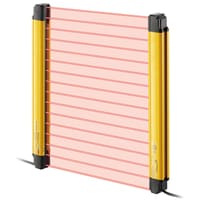


GL-RHG Detection capability ø25mm:Total length 1440 to 1920mm
|
Model |
GL-R72HG |
GL-R80HG |
GL-R88HG |
GL-R96HG |
|||
|
Image |
|
|
|
|
|||
|
Detection capability |
ø25 mm |
||||||
|
Total length |
1440mm |
1600mm |
1760mm |
1920mm |
|||
|
No. of beam |
72 |
80 |
88 |
96 |
|||
|
Detection height |
1465 mm |
1625 mm |
1785 mm |
1945 mm |
|||
|
Protection height |
1420 mm |
1580 mm |
1740 mm |
1900 mm |
|||
|
Beam axis spacing/Lens diameter |
20 mm / ø5 |
||||||
|
Detecting distance |
0.2 to 15 m*1 |
||||||
|
Effective aperture angle |
Max. ±2.5° (When operating distance is 3 m or more) |
||||||
|
Light source |
Infrared LED (870 nm) |
||||||
|
Response time (OSSD) (ms) |
Wire synchronisation, One-line or |
ON→OFF |
12.2 |
13.1 |
13.9 |
14.8 |
|
|
OFF→ON |
57.1*2 |
58.4*2 |
59.7*2 |
61*2 |
|||
|
All blocked→ON |
85.6*3 |
89.1*3 |
92.5*3 |
96*3 |
|||
|
Optical synchronisation system |
ON→OFF |
17.8 |
19.2 |
20.6 |
22 |
||
|
OFF→ON |
65.5*2 |
67.6*2 |
69.7*2 |
71.8*2 |
|||
|
All blocked→ON |
108.1*3 |
113.7*3 |
119.2*3 |
124.8*3 |
|||
|
Detection mode |
Turned on when light is being applied to all optical axes |
||||||
|
Synchronisation between the transmitter and receiver |
Optical synchronisation or Wire synchronisation (Determined by wiring) |
||||||
|
Light interference prevention function |
Prevents mutual interference in up to two GL-R systems. |
||||||
|
Control output |
Output |
2 transistor outputs. (PNP or NPN is determined by the cable type) |
|||||
|
Max. load current |
500 mA*4 |
||||||
|
Residual voltage (during ON) |
Max. 2.5 V (with a cable length of 5 m) |
||||||
|
OFF state voltage |
Max. 2.0 V (with a cable length of 5 m) |
||||||
|
Leakage current |
Max. 200 µA |
||||||
|
Max. capacitive load |
2.2 µF |
||||||
|
Load wiring resistance |
Max. 2.5 Ω |
||||||
|
Supplemental output |
AUX |
transistor outputs. (PNP or NPN is determined by the cable type) |
|||||
|
Error output |
|||||||
|
Muting lamp output |
Incandescent lamp (24 VDC, 1 to 5.5 W) |
||||||
|
External input |
When using a PNP output cable |
EDM input |
ON voltage: 10 to 30 V |
||||
|
When using an NPN output cable |
EDM input |
ON voltage: 0 to 3 V |
|||||
|
Power supply |
Power voltage |
24 VDC ±20%, ripple (P-P) 10% or less, Class 2 |
|||||
|
Current |
Transmitter |
75 |
77 |
79 |
81 |
||
|
Receiver |
85 |
87 |
89 |
91 |
|||
|
Protection circuit |
Reverse current protection, short-circuit protection for each output, surge protection for each output |
||||||
|
Approved standards |
EMC |
EMS |
IEC61496-1, EN61496-1, UL61496-1 |
||||
|
EMI |
EN55011 ClassA, FCC Part15B ClassA, ICES-003 ClassA |
||||||
|
Safety |
IEC61496-1, EN61496-1, UL61496-1 (Type 4 ESPE) |
||||||
|
Environmental resistance |
Enclosure rating |
IP65/IP67 (IEC60529) |
|||||
|
Overvoltage category |
II |
||||||
|
Ambient light |
Incandescent lamp: 3,000 lux or less, Sunlight: 20,000 lux or less |
||||||
|
Operating ambient temperature |
-10 to +55 °C (No freezing) |
||||||
|
Operating relative humidity |
15 to 85 % RH (No condensation) |
||||||
|
Storage temperature |
-25 to +60 °C (No freezing) |
||||||
|
Storage relative humidity |
15 to 95 % RH |
||||||
|
Vibration resistance |
10 to 55 Hz, Double amplitude 0.7 mm, 20 sweeps in each of the X, Y, and Z directions |
||||||
|
Shock resistance |
100 m/s2 (Approx. 10 G), 16 ms pulse, 1,000 times in each of the X, Y, and Z directions |
||||||
|
Material |
Main unit case |
Aluminium |
|||||
|
Upper case/lower case |
Nylon (GF 30%) |
||||||
|
Front cover |
Polycarbonate, SUS304 |
||||||
|
Weight |
Transmitter |
2010 g |
2230 g |
2450 g |
2680 g |
||
|
Receiver |
2240 g |
2460 g |
2690 g |
||||
|
*1 When the option front protection cover is installed on the one of transmitter or receiver, the Operating distance is shorten by 0.5 m. When the front covers are installed on both of the transmitter and receiver, the Operating distance is shorten by 1.0 m. |
|||||||